Paired warp triple layer forming fabrics with optimum sheet building characteristics

a technology of building characteristics and paired warps, applied in the field of forming fabrics, can solve the problems of short fabric life, inability to spread the crossover points far enough apart to eliminate this strong topographical defect, and suffer from poor sheet quality and machine efficiency, so as to reduce the number of looms. the effect of reducing the number of looms

Inactive Publication Date: 2006-05-23
ALBANY INT CORP
View PDF52 Cites 43 Cited by
  • Summary
  • Abstract
  • Description
  • Claims
  • Application Information

AI Technical Summary

Benefits of technology

[0024]The fabric is disposed on the forming section in endless form. The invention's fabric pattern minimizes drainage and topographical markings which result from the arrangement of the warp crossover points and the alignment of the yarns in each crossing pair. This is achieved by like adjacent yarns from adjacent pairs having MD cell lengths greater than or less than MD cell lengths from non-like adjacent yarns from adjacent pairs. In a particularly useful case, when the crossover point repeat pattern length in the CD can be divided into the CD weave pattern repeat and the outcome is a multiple of two, and like yarns in crossovers along the same CD line extend in opposite directions, the pattern can be woven on a loom with half the number of frames for a pattern repeat if the loom is threaded in a “fancy” draw. This is advantageous to the manufacturer since lower cost and less complex looms are needed.

Problems solved by technology

However, forming fabrics also need to address water removal and sheet formation issues.
If drainage occurs too rapidly or too slowly, the sheet quality and machine efficiency suffers.
The disadvantages of Österberg, Vöhringer and Johansson are either strong topside diagonals or strong drainage diagonals formed from how the yarns cross each other and align in the woven cloth.
Unfortunately, when using 100% paired integral MD yarns, it is impossible to spread the crossover points far enough apart to eliminate this strong topographical defect formed by the crossover points lining up in a diagonal pattern.
A fine mesh fabric may provide the desired paper surface properties, but such design may lack the desired stability resulting in a short fabric life.
One problem with triple layer fabrics has been relative slippage between the two layers which breaks down the fabric over time.
In addition, the binding yarns can disrupt the structure of the forming layer resulting in marking of the paper.

Method used


Image

  • Paired warp triple layer forming fabrics with optimum sheet building characteristics
  • Paired warp triple layer forming fabrics with optimum sheet building characteristics
  • Paired warp triple layer forming fabrics with optimum sheet building characteristics

Examples


Embodiment Construction

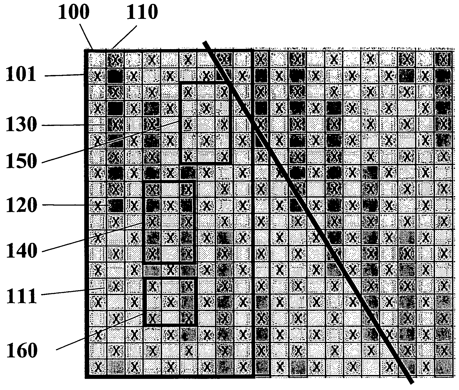
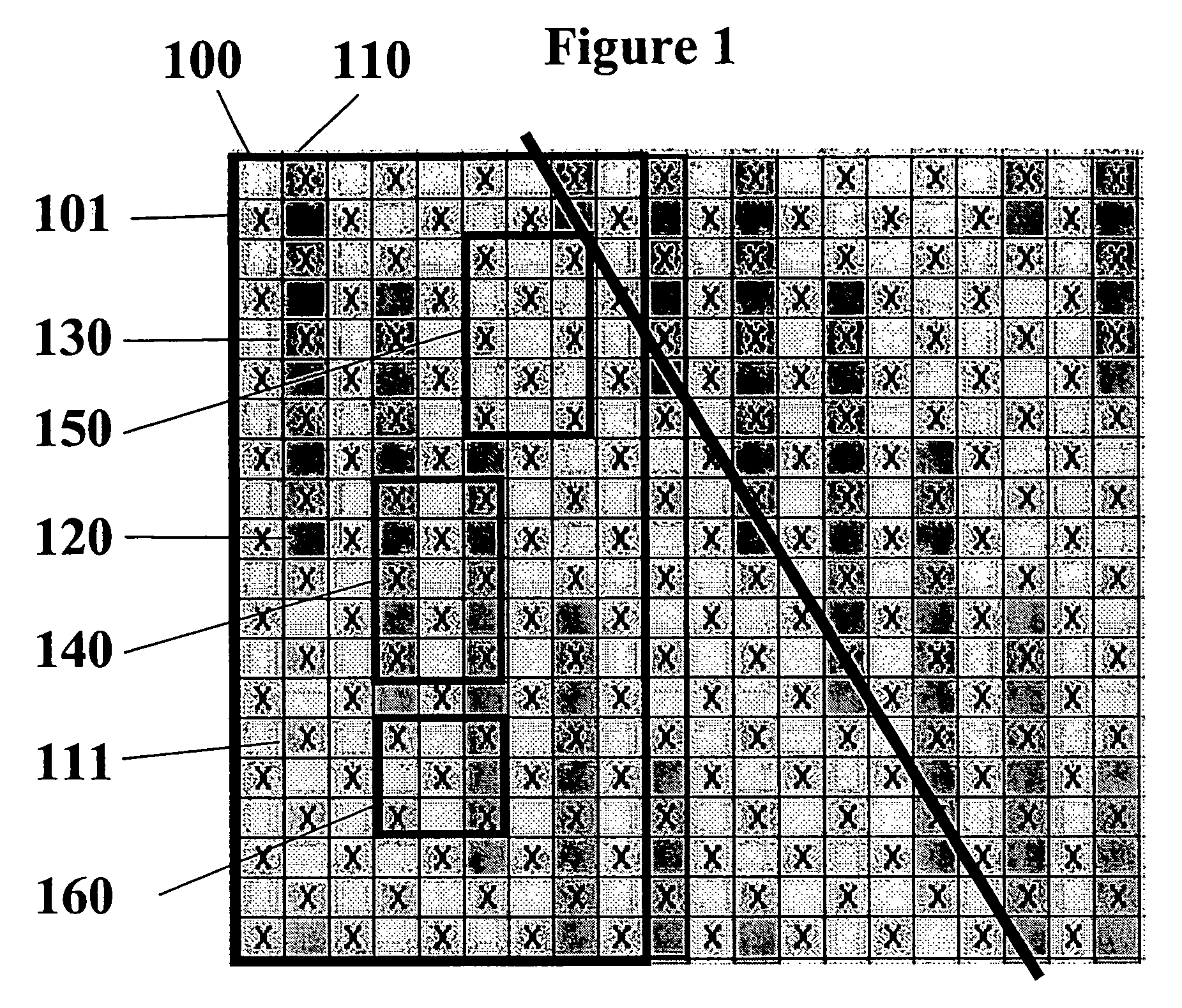
[0042]To counter the strong diagonal crossover pattern 310 exhibited by the fabrics taught in the Johansson patent shown in FIG. 3, the present invention weaves a second MD yarn pair between the crossing pairs to spread the crossover points. At least one of the yarns in this second pair will be part of the forming side weave pattern. These additional yarns result in a second warp system and the resulting fabric structure becomes a triple layer. The crossing pairs now make up binding yarns that bind the top and bottom sides together and are an integral part of the topside weave. To add necessary MD tensile strength a third warp system is added below the second warp system. This third warp system makes up the wear-side of the cloth with the crossing pairs either binding the wear-side or acting as an integral part of this bottom side weave.

[0043]FIG. 1 shows an example of a forming side (FS) plan view of a paired warp fabric in a satin crossover arrangement with left and right warp yar...


PUM


Abstract

A papermaker's fabric, usable in the forming section of a paper machine, having two layers of cross-machine-direction (CD) yarns. Interwoven with the CD yarns is a system of MD yarns. At least some of the MD yarns are grouped into alternating pairs comprising a crossing pair having a first MD yarn and a second MD yarn and a second pair having a third MD yarn and a fourth MD yarn. The first MD yarn and the second MD yarn combine to weave each CD yarn in the first layer and cross between the first layer and the second layer. The left and right warp yarns in the pairs are aligned in such a way that like adjacent yarns from adjacent pairs have MD cell lengths greater than or less than the MD cell lengths from non-like adjacent yarns from adjacent pairs. The third MD yarn is interwoven with the first layer of CD yarns and the fourth MD yarn is interwoven with the second layer of CD yarns. In this manner, a paired warped triple layer forming fabric may be produced which minimizes drainage and crossover point topographical markings.

Description

[0001]This application is a continuation-in-part of U.S. application Ser. No. 10 / 279,634, filed Oct. 24, 2002 now U.S. Pat. No. 6,834,684.BACKGROUND OF THE INVENTION[0002]1. Field of the Invention[0003]The present invention relates to the papermaking arts. More specifically, the present invention relates to forming fabrics for the forming section of a paper machine.[0004]2. Description of the Prior Art[0005]During the papermaking process, a cellulosic fibrous web is formed by depositing a fibrous slurry, that is, an aqueous dispersion of cellulose fibers, onto a moving forming fabric in the forming section of a paper machine. A large amount of water is drained from the slurry through the forming fabric, leaving the cellulosic fibrous web on the surface of the forming fabric.[0006]The newly formed cellulosic fibrous web proceeds from the forming section to a press section, which includes a series of press nips. The cellulosic fibrous web passes through the press nips supported by a p...

Claims


Application Information

Patent Timeline
Patent Type & Authority Patents(United States)
IPC IPC(8): D03D41/00D21F1/00
CPCD21F1/0045D21F1/00
Inventor MARTIN, CHAD A.QUIGLEY, SCOTT
Owner ALBANY INT CORP
Why Eureka
Try Eureka