
Apparatus for casting dental prosthesis

a dental prosthesis and casting technology, applied in the field of casting dental prostheses, can solve the problems of inability to obtain the desired quality of the prosthesis, defective prosthesis pieces, and time-consuming and labor-intensive casting work, and achieve the effects of easy inspection, high degree of safety, and large imag

Inactive Publication Date: 2006-05-23
DENKEN
View PDF4 Cites 12 Cited by
  • Summary
  • Abstract
  • Description
  • Claims
  • Application Information

AI Technical Summary

Benefits of technology

[0024]Using the gripper, the present apparatus performs a position-correcting motion as follows. First, the gripper is lowered to a level close to the bottom of the ring. Then, the gripping operation as described above is performed with the gripper. In the gripping operation, the gripper pushes the ring from the outside or inside until the ring reaches the gripping point of the gripper, e.g. center of the rods. Thus, the ring can be brought to the correct position. It is not preferable to perform such a correcting operation with the gripper located at a level close to the upper end of the ring; when pushed in the upper part, the ring will fall down if it is greatly displaced from the correct position. Lowering of the gripper to a level close to the bottom of the ring effectively prevents such an occurrence. Thus, the present apparatus can assuredly correct the position of the ring on the ring-placing section.
[0059]Thus, the apparatus according to the fifth aspect of the invention allows the operator to check the molten state of the casting material in the crucible from the outside of the casing, if necessary. Therefore, even when a casting material whose melting conditions are unknown or uncertain is used, it is possible to perform the pouring process after ascertaining that the casting material is adequately melted. The molten state can be checked from the outside of the casing, which provides a high degree of safety.

Problems solved by technology

Therefore, when various forms of prostheses are to be manufactured, it is necessary to spend a considerable amount of time and labor to carry out the casting work as described above.
Further, the temperatures and time periods for burning the ring and for melting the metal must be appropriately determined depending on the selection of the investment material and alloy material, because a desired quality of prosthesis cannot be obtained when the settings are inappropriate.
Conventionally, however, some pieces of prosthesis result in being defective (e.g. missing a part) as a result of inappropriate settings of the apparatuses, wrong order of work and / or accidental omission of work.
Though the above apparatus can automatically perform the burning and pouring, it cannot perform the basic work of setting rings and crucibles in the apparatus, which must be manually performed by the operator.
Therefore, it is possible that the operator accidentally makes a mistake or omits a work process.
Another problem, which is less serious than the aforementioned cases, is that the personal differences or other kinds of unevenness in the manner of working may cause a defect in the prosthesis, decrease the working efficiency or increase the manufacturing costs.
A displacement of the ring from the predetermined position often leads to the incorrect gripping of the ring by a gripping device (which is called the “gripper” hereinafter), which may make the ring fall down in the gripping process.
This, however, requires a mechanism for moving the pins, which accordingly increases the production costs.
Ceramic crucibles gradually become brittle when they are repeatedly used.
The possibility of cracking or breaking of the crucible rapidly increases when it is used more than approximately twenty times. If such a problem occurs in the course of the pouring process, it is necessary to not only stop the work but also perform other unnecessary work, such as the removal of the scattered casting material.
If such residues are not removed, the ring placed on the lifting stage may be tilted by a piece of residue lying underneath, causing it to be on the verge of falling down or other hazardous situation.
Accordingly, the operator must frequently take the trouble to clean the lifting stage to remove the residues.
Neglecting this job may eventually lead to a discontinuation of the casting work.
If this happens, the pouring cannot be correctly performed, which wastes not only time but also the casting material.
To do such a visual check with conventional apparatuses, the operator is required to lean over the apparatus to look into the crucible, which is not only troublesome but also unsafe.

Method used


Image

  • Apparatus for casting dental prosthesis
  • Apparatus for casting dental prosthesis
  • Apparatus for casting dental prosthesis

Examples


Embodiment Construction

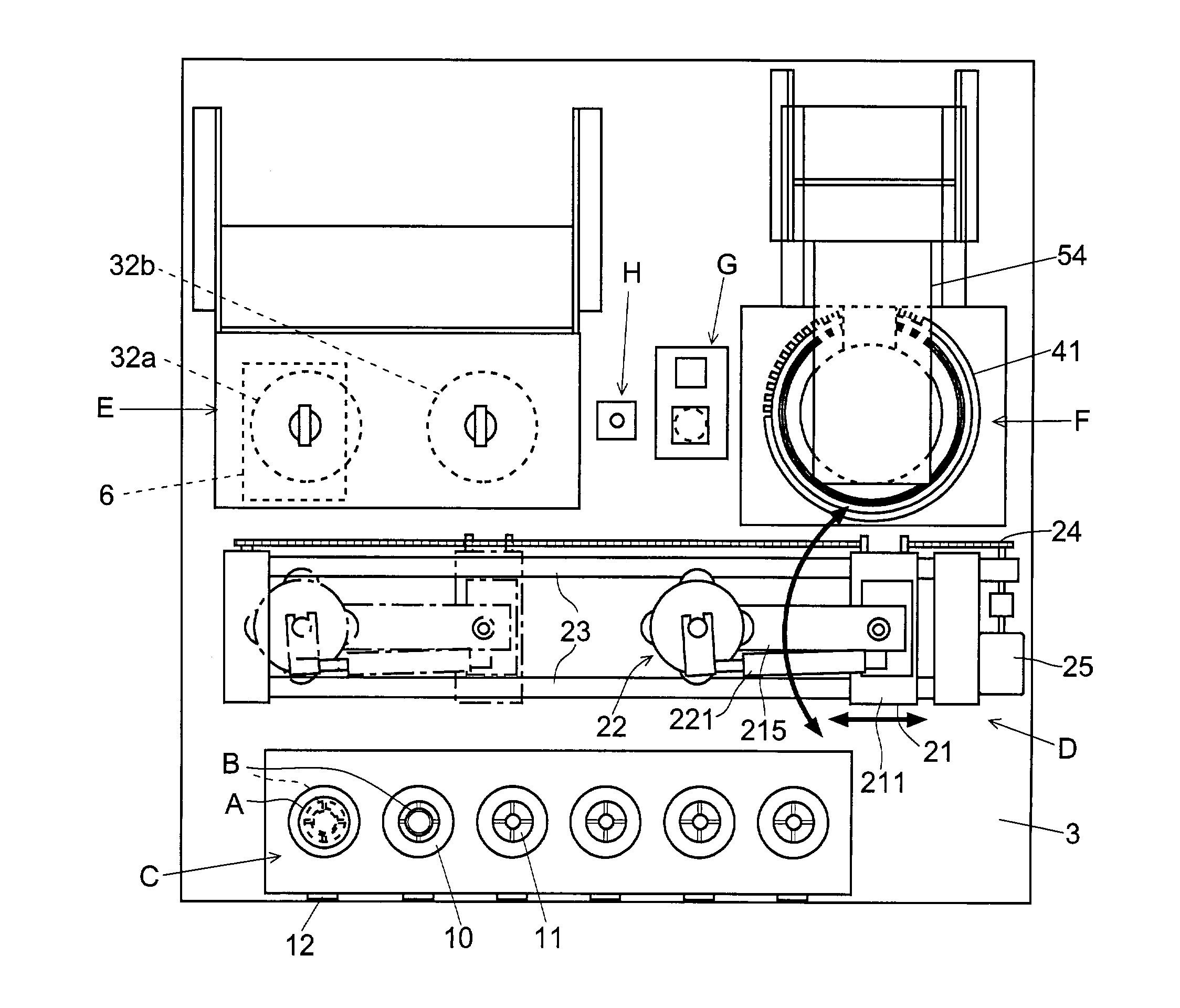
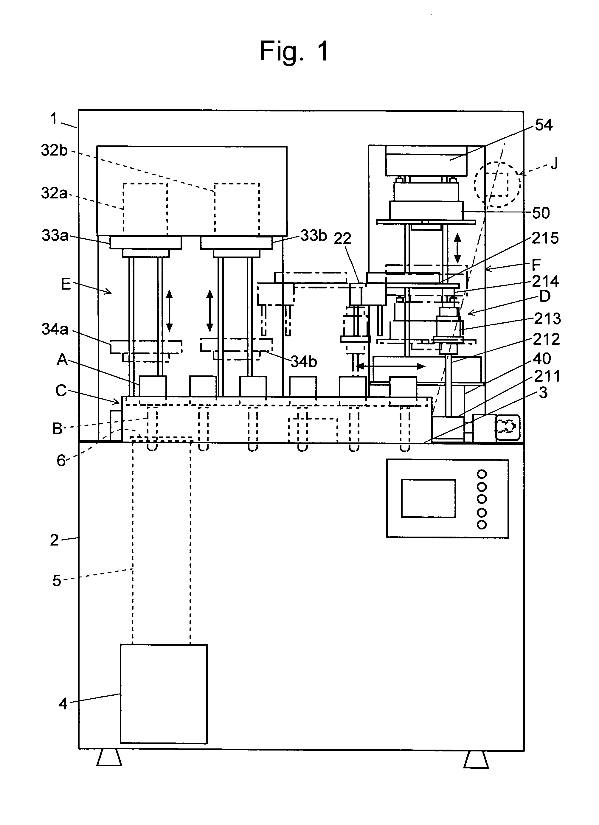
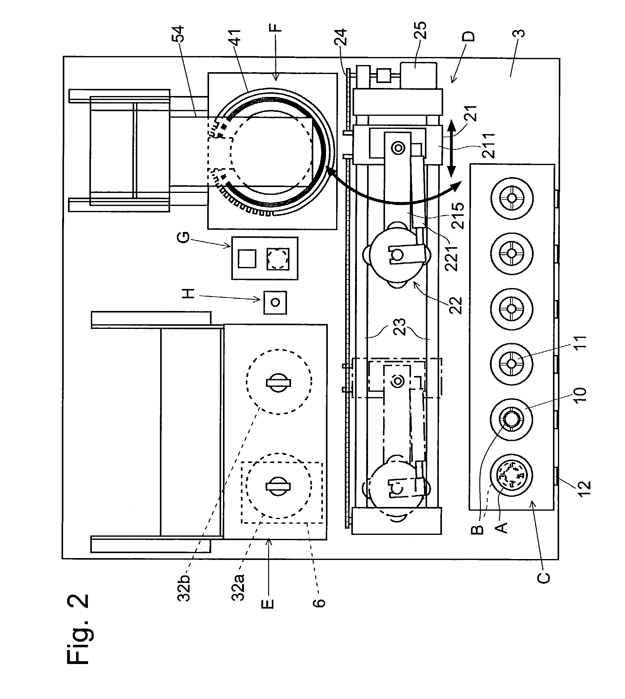
[0073]An automatic casting apparatus as an embodiment of the present invention is described below, referring to the attached drawings.

[0074]As shown in FIGS. 1 and 2, the casting apparatus has a long rectangular body, the lower part of which is a box 2 containing a control circuit for controlling the mechanical and electrical operations, and mechanisms for supplying compressed air. The top of the box 2 serves as a table 3 on which several devices are mounted for various kinds of work, which will be described later. The top of the table 3 is covered with a cover 1 having a transparent door (not shown) at its front side. The cover 1 ensures the safety of the operator, and prevents litters, dusts and other foreign matters from falling onto the table 3.

[0075]On the table 3, a ring / crucible-placing platform C, having the capacity of six rings A and six crucibles B, is provided at the front, and a conveyer D for holding and conveying the ring A or crucible B is provided behind the ring / cr...


PUM

PropertyMeasurementUnit
Forceaaaaaaaaaa

Abstract

A new apparatus for casting dental prosthesis has been proposed, comprising a ring-placing section onto which plural rings are to be placed, a crucible holder for holding plural cylindrical crucibles, a burning unit with a furnace, a casting unit and a conveyer for conveying the ring or the crucible. The lifting state of the burning unit includes a base capable of rotating around a substantially horizontal axis, an orientation-maintaining mechanism for maintaining the base substantially horizontal and an orientation-changing mechanism for exerting an external force onto the base. The conveyer performs a position-correcting motion for correcting the position of the ring by lowering the gripper. The apparatus provides a management code to each crucible for preventing troubles or delay of work caused by the breaking of crucibles due to the aging.

Description

[0001]The present invention relates to a casting apparatus for manufacturing dental prostheses, such as inlay, crown, base, implant, and upper parts of implants, from precious metals or non-precious metals.BACKGROUND OF THE INVENTION[0002]The lost wax process is a conventionally known method of manufacturing dental prostheses from precious metals or non-precious metals. FIG. 12 is a flowchart showing the process of dental casting according to the lost wax method.[0003]First, a dentist or other individual takes a negative impression model of the mouth and teeth around the object part of a patient (Step S1). Using the negative impression, a dental technician manufactures a dental prosthesis as follows. First, a modeling material, such as gypsum, is poured into the negative impression, and solidifies the material to produce a positive model (Step S2). A desired type of casting model, such as an inlay or crown, for the positive model is created with a heat-subliming material, such as wa...

Claims


Application Information

Patent Timeline
IPC IPC(8): B22D41/00A61C13/20B22C9/04B22D18/06B22D41/04B22D46/00B22D47/02
CPCA61C13/20B22D46/00B22D41/04B22D18/06
Inventor USUI, MASAKI
Owner DENKEN
Learn More