High-voltage electrical equipment case arranging structure

Inactive Publication Date: 2006-05-23
HONDA MOTOR CO LTD
View PDF43 Cites 69 Cited by
  • Summary
  • Abstract
  • Description
  • Claims
  • Application Information

AI Technical Summary

Benefits of technology

[0006]Consequently, an object of the invention is to provide a high-voltage electrical equipment case arranging structure

Problems solved by technology

Additionally, in the structure where the battery is placed underneath the rear seat, the battery so placed tends to constitute an interruption to a

Method used


Image

  • High-voltage electrical equipment case arranging structure
  • High-voltage electrical equipment case arranging structure
  • High-voltage electrical equipment case arranging structure

Examples


Embodiment Construction

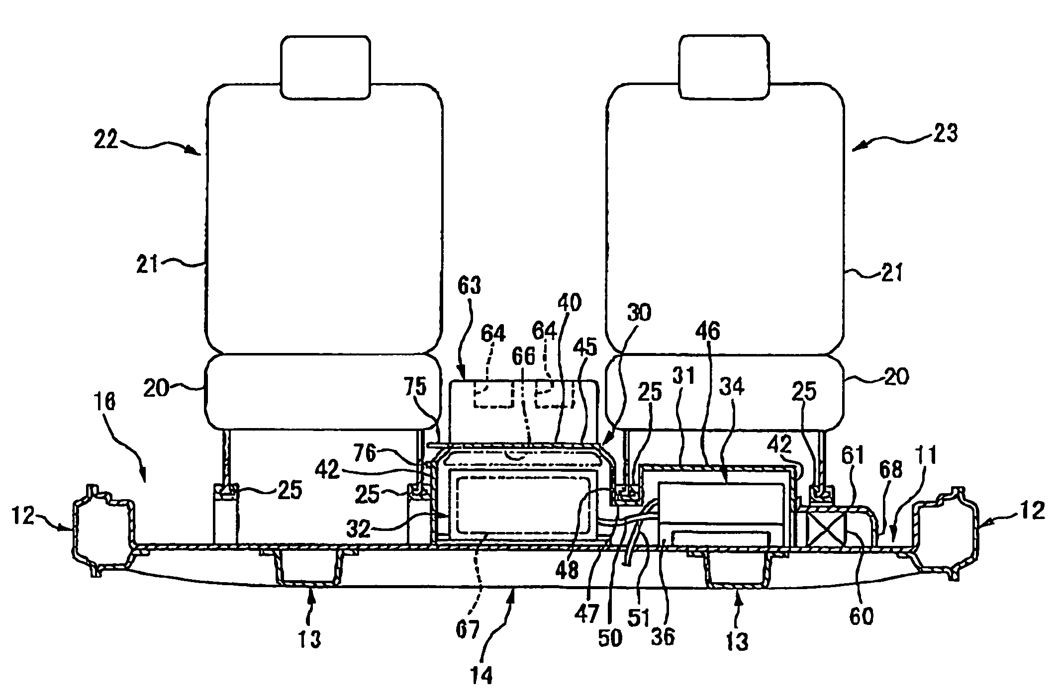
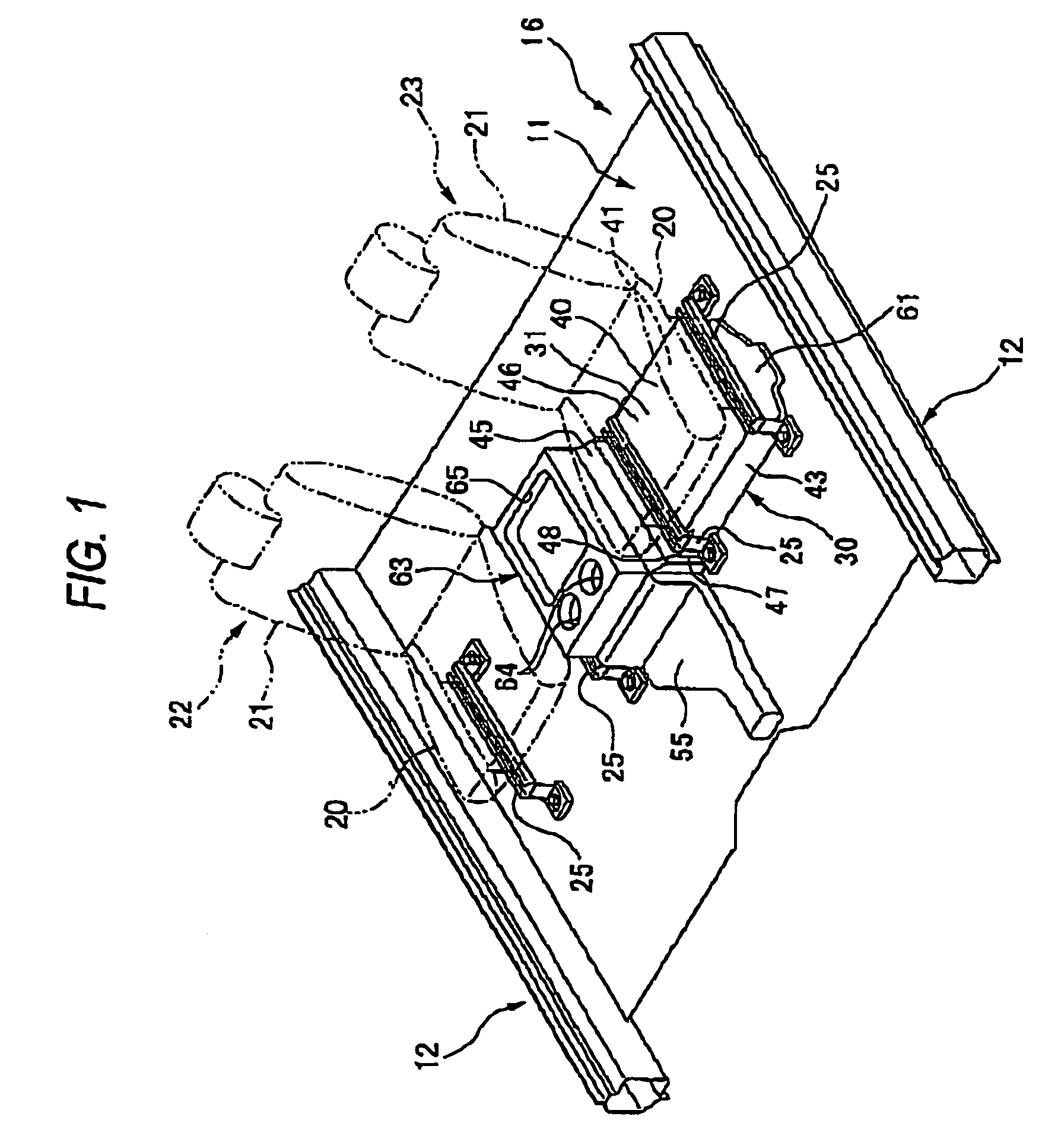
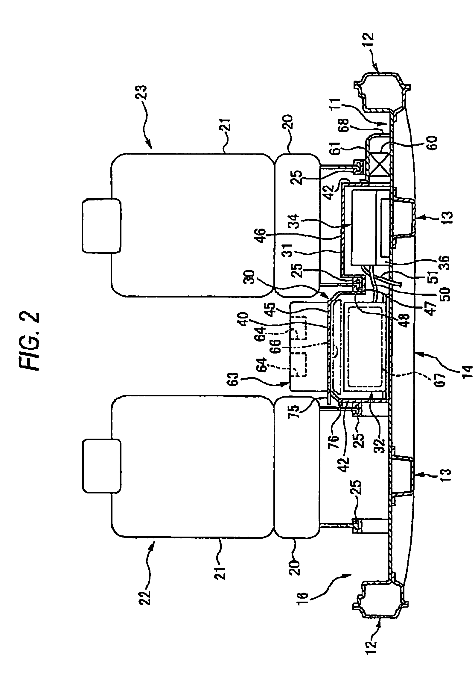
[0021]An embodiment of a high-voltage electrical equipment case arranging structure according to the invention will be described below by reference to the accompanying drawings. Note that when used herein, direction indicating terms such as front, rear, left and right denote, front, rear, left and right to a forward traveling vehicle.

[0022]This embodiment illustrates an example where the invention is applied to a hybrid vehicle which runs by appropriately controlling the driving force of an internal combustion engine, not shown, and the driving force of a running electric motor, also not shown, and in the drawings, reference numeral 11 denotes a floor panel of the vehicle. As shown in FIGS. 1 and 2, side sills 12 (framework portions of the vehicle body) having cross sections intersecting with the longitudinal direction at right angles are formed into a closed shape and are formed on transversely outer sides of the floor panel 11 in such a manner as to extend in the longitudinal dire...


PUM


Abstract

A high-voltage electrical equipment case is arranged between a driver's seat and a front passenger's seat which are placed in parallel in a transverse direction, whereby in the event that the battery which is a heavy article is accommodated in this high-voltage electrical equipment case, a necessity is obviated of disposing the battery underneath a rear seat. Moreover, the high-voltage electrical equipment case can be disposed near an air conditioner that is installed in a front part of a vehicle.

Description

BACKGROUND OF THE INVENTION[0001]1. Field of the Invention[0002]The present invention relates to a high-voltage electrical equipment case arranging structure.[0003]2. Description of the Related Art[0004]With respect to a high-voltage electrical equipment arranging structure on a vehicle body floor, there has been proposed a technique in which motor control units for controlling running motors are placed underneath a driver's seat and a front passenger's seat, respectively, and a battery for storing electric power for the running motors is provided underneath a rear seat (refer, for example, to JP-7-112620).[0005]In the aforesaid structure where the motor control units are provided underneath the driver's seat and the front passenger's seat, respectively, and the battery is provided underneath the rear seat, since the heavy portions are dispersed when set in place, a good weight distribution can not be realized for the vehicle, and therefore, there is a ground for further improvement...

Claims


Application Information

Patent Timeline
IPC IPC(8): B60N3/12B60N2/75B60N3/10B60R16/02B60R16/023
CPCB60N2/468B60R16/0239B60N3/101B60N2/4686B60H2001/003B60N2/79B60N2/793B60L50/64Y02T10/70
Inventor BANDOH, MASASHINAGANUMA, ATSUHIROOYA, SATOYOSHI
Owner HONDA MOTOR CO LTD
Why Eureka
Try Eureka