Machine tool apparatus

a technology of machine tools and tools, applied in the direction of driving apparatus, boring/drilling components, manufacturing tools, etc., can solve the problems of complex feed mechanism, large program expenditure, complicated machining control, etc., and achieve the effect of optimally setting the feed of the machining tool

Inactive Publication Date: 2006-05-23
AISIN AW CO LTD
View PDF19 Cites 3 Cited by
  • Summary
  • Abstract
  • Description
  • Claims
  • Application Information

AI Technical Summary

Benefits of technology

[0009]In light of the above described problems, it is an object of the invention to provide a machine tool apparatus that, while machining a workpiece, feed control of the machining tool can be more simply executed and to provide a feed mechanism for the machining tool that is less complicated.
[0011]Accordingly, particularly when performing oblique machining, it is not necessary to execute simultaneous three-dimensional control, i.e., control along three axes, namely, the X, Y and Z axes, as is conventionally the case, and it is therefore possible to simplify control of the feed of the machining tool. Further, as a result of the above, the programs for feed control of the machining tool can be made simpler, and it is possible to reduce software cost since the complicated programs conventionally used are no longer required.
[0012]In addition, since feed control of the machining tool in three dimensions (the X, Y and Z axes) is not necessary, as described above, it is possible to simplify the feed mechanism of the machining tool. Accordingly, for the feed mechanism, it is no longer essential to use a complicated and expensive device that can move the machining tool in three (axial) dimensions, as was conventionally the case. Thus, hardware costs can also be reduced.
[0013]Further, more particularly, according to one preferred embodiment of the invention, it is possible to drive both the machining tool and the feed mechanism using rotation of the spindle alone. Such a configuration is beneficial, for example, in the case of a rotating machining tool which is fed along the rotational axis and which is used in applications (like a milling drill for which accurate feed speed control is unnecessary) other than, for example, a hole-drilling operation wherein the inner peripheral surface of an already formed hole is milled. Further, a paired-bevel gear mechanism, including a bevel drive gear and a bevel driven gear, may be used alone. Accordingly, the number of components can be reduced and the configuration can be simplified.
[0015]Any preferred embodiment may use a screw movement conversion mechanism, making it possible to optimally set feed of the machining tool, by appropriately setting the pitch of a screw portion of the screw movement conversion mechanism.

Problems solved by technology

Accordingly, the machining control is complicated and cumbersome, and a large number of different programs for feed control of the machining tool are necessary.
As a result, the expenditure on programs is substantial.
Moreover, the feed mechanism is also complicated since it is necessary to execute movement in three axial directions, namely, the two axial directions (the X and Y axes) in which a table is moved, and the spindle (the Z axis) direction.

Method used


Image

  • Machine tool apparatus
  • Machine tool apparatus
  • Machine tool apparatus

Examples


Embodiment Construction

[0019]Hereinafter, a preferred embodiment of the invention will be explained with reference to the drawings.

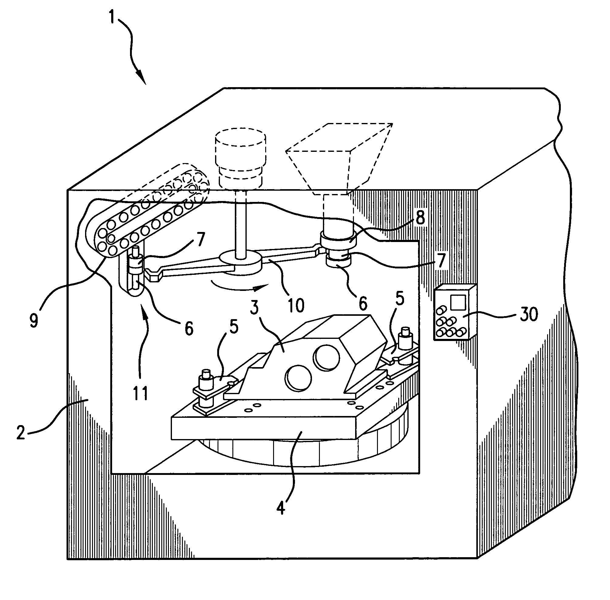
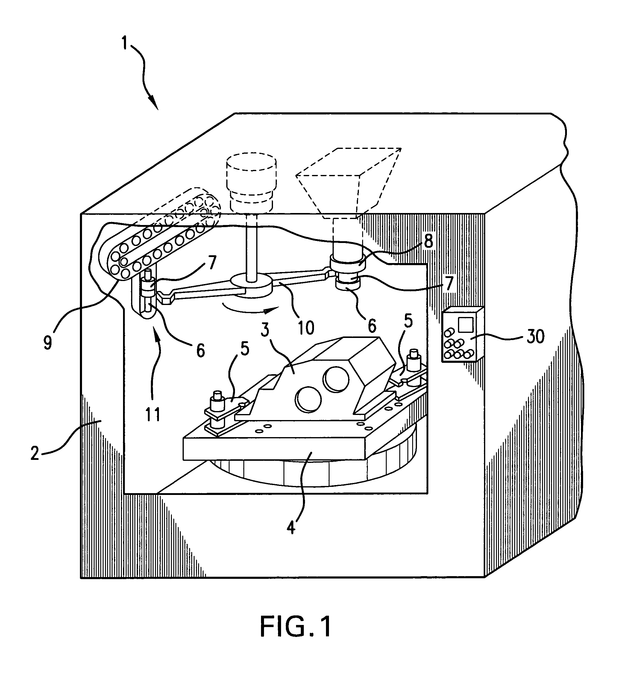
[0020]FIG. 1 shows a preferred embodiment of the machine tool (hereinafter referred to as “M / C”) 1 as including body 2, a table 4 that fixedly supports a workpiece 3, a clamp device 5 that fixes the workpiece 3 to the table 4, tool holders 7 (which correspond to the “machining tool holding unit” of the invention) which hold various removable tools 6, a spindle 8, a tool storage unit 9, and an automatic tool changer 10. Respective tool holders 7 are removably mounted on the spindle 8, which utilizes the respective functions of the tools 6 through transmission of rotation thereto. The tool storage unit 9 stores the tool holders 7. The automatic tool changer 10 automatically removes the tool holder 7 mounted on the spindle 8 at any given time and stores it in the tool storage unit 9, and then automatically mounts on the spindle 8 another of the tool holders 7 (which holds the too...


PUM

PropertyMeasurementUnit
rotational speed ratioaaaaaaaaaa
rotational speedaaaaaaaaaa
axis of rotationaaaaaaaaaa

Abstract

A machining tool has a tool holder aligned on an axis of rotation β of its shaft, which axis β is oblique to the axis of rotation of a spindle at a predetermined angle θ. Accordingly, the machining tool may perform oblique machining of a workpiece. A power transmission mechanism that transmits rotation of the spindle to the machining tool is formed as an attachment to the spindle and includes a rotatable shaft, a second bevel drive gear, a second bevel driven gear, and a feed shaft. Further, a feed mechanism which feeds the machining tool along the axis β of the rotatable shaft is formed of the attachments, the rotatable shaft; the second bevel drive gear and the second bevel driven gear, a first bevel drive gear a first bevel driven gear, a male screw member, and the feed shaft.

Description

CROSS-REFERENCE TO RELATED APPLICATION[0001]This application claims, under 35 USC 119, priority of Japanese Application No. 2003-203168 filed Jul. 29, 2003.INCORPORATION BY REFERENCE[0002]The disclosure of Japanese Patent Application No. 2003-203168 filed on 29 Jul., 2003 including the specification, drawings and abstract is incorporated herein by reference in its entirety.BACKGROUND OF THE INVENTION[0003]1. Field of the Invention[0004]The invention relates to a machine tool apparatus (machining center) for machining a workpiece, and more particularly to a machining apparatus provided with a machine tool holder that is replaceably mounted on or in a spindle.[0005]2. Description of the Related Art[0006]Conventionally, a machine tool apparatus performs various types of machining operations on workpieces, for example, components of an automatic transmission (hereinafter referred to as “A / T”). These machining operations include at least one process performed in a direction that is obliq...

Claims


Application Information

Patent Timeline
Patent Type & Authority Patents(United States)
IPC IPC(8): B23B47/18B23Q5/04B23Q1/00B23Q5/22B23Q15/013
CPCB23Q5/045B23Q5/046B23Q5/326Y10T408/73Y10T408/6793Y10T408/68Y10T409/309296
Inventor MURAI, KAZUTAKASHIRATO, NOBUAKI
Owner AISIN AW CO LTD
Why Eureka
Try Eureka