Method and apparatus for smoothing unfinished surfaces
a technology for unfinished surfaces and edges, applied in the field of carpentry tools, can solve the problems of destroying products, sanding and polishing of more complex surfaces, and no sander currently available, and achieve the effect of high flexibility and efficiency
- Summary
- Abstract
- Description
- Claims
- Application Information
AI Technical Summary
Benefits of technology
Problems solved by technology
Method used
Image
Examples
second embodiment
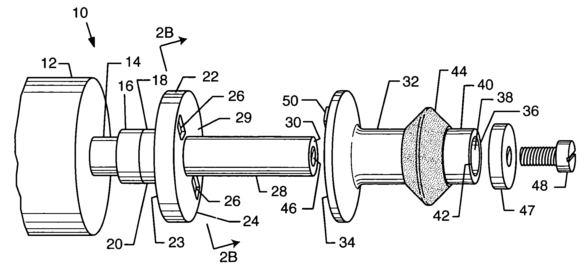
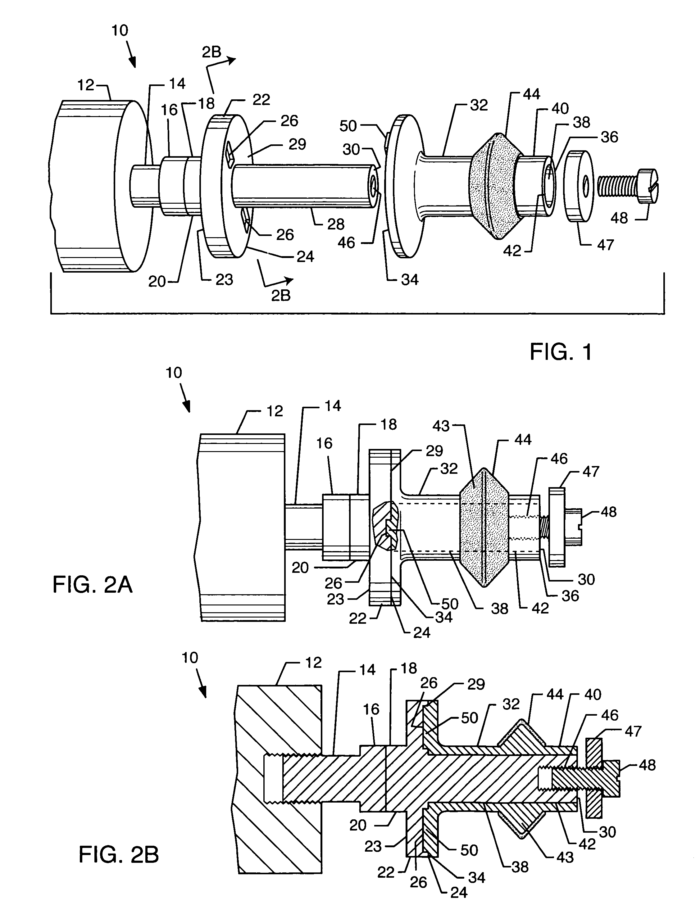
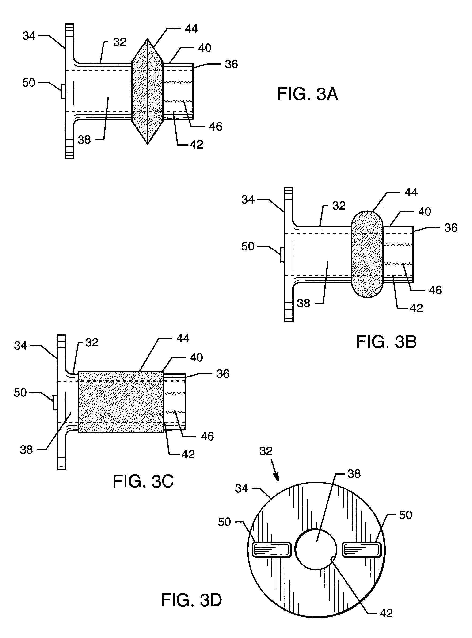
[0044]FIG. 5 illustrates the present invention. While similar in many respects to the preferred embodiment of the invention described above, I have adapted a different product for use so that the sanding heads can be made to match the size and shape of the standard ¼-inch router heads currently available on the market. It also uses the standard router guide bearing 56 that would allow it to be used to surface the area that a router has previously cut. In addition, it could be used to round the corners of a small box or soft wood that a normal router head would splinter. Guide bearing 56 is mounted to the unit at second end wall 30 of mandrel 18 and secured to the unit by fastener 48. The sanding heads can be formed into shapes that match the compound curves of some of the router heads, which would then allow the cleaning of an area that a router might have missed or that have become uneven. Abrasive material 44 on sanding head 32 shown in FIG. 5 would be formed in the multiple shape...
third embodiment
[0047]the present invention is illustrated in FIG. 7, which enables the use of standard sanding tubes currently available on the market. In this embodiment, the extension 58 is sized so that the overall length of drive shaft 28 and extension 58 total a length of 4½ inches and a diameter of ½-inch, which is the length and diameter required to accommodate a standard sanding tube. FIG. 7 shows sanding tube 58 in place. Sanding tube 68 may be secured to drive shaft 28 and extension 68 by using an appropriately sized washer (not shown) and inserting a threaded connector (not shown) into receiving port 66.
[0048]If a user so desires, hollow handle 72 may be secured to extension 58 by threading handle fastener 76 into threaded receiving port 66. Thrust bearing 74 is embedded in handle 72 to allow the handle to turn freely during operation.
[0049]Two sanding tubes 68 may be used in this application by attaching additional extensions as needed to make the overall length of the drive shaft 9 in...
fourth embodiment
[0051]the present invention is illustrated in FIG. 8A, which utilizes a paint roller 78 mounted to drive shaft 28. This embodiment of the invention is ideal for polishing surfaces such as skis, snowboards, and hand rails, among other applications. In order to secure paint roller 78 to drive shaft 28, plastic end caps 80 and 90 are inserted in opposing ends of the paint roller. FIG. 8B illustrates the configuration of the two end caps. Flanged end cap 80 is constructed with locking flanges 86 on first side 82 to secure paint roller 78 to locking receptacles 26 in drive plate 22. Opening 88 in flanged end cap 80 allows paint roller 78 to slide over drive shaft 28. Outer cap 90 is inserted in the opposite end of paint roller 78. Outer cap 90 includes orifice 98, which is sized to slide over drive shaft 28. Roller handle 100 is secured to drive shaft 28 by inserting roller handle screw 102 into threaded receiving port 66. Use of the roller handle 100 in conjunction with paint roller 78 ...
PUM
| Property | Measurement | Unit |
|---|---|---|
| shape | aaaaa | aaaaa |
| size | aaaaa | aaaaa |
| shapes | aaaaa | aaaaa |
Abstract
Description
Claims
Application Information
 - R&D
- Intellectual Property
- Life Sciences
- Materials
- Tech Scout
- Unparalleled Data Quality
- Higher Quality Content
- 60% Fewer Hallucinations
Browse by: Latest US Patents, China's latest patents, Technical Efficacy Thesaurus, Application Domain, Technology Topic, Popular Technical Reports.
© 2025 PatSnap. All rights reserved.Legal|Privacy policy|Modern Slavery Act Transparency Statement|Sitemap|About US| Contact US: help@patsnap.com


