

Internal antenna
a technology for antennas and antenna supports, applied in the structural forms of antennas, antenna supports/mountings, radiating elements, etc., can solve the problems of limiting the useful range of devices, efficiency losses, and waste of radiation of a pcb placed next to the user's head
- Summary
- Abstract
- Description
- Claims
- Application Information
AI Technical Summary
Benefits of technology
Problems solved by technology
Method used
Image

Examples
Embodiment Construction
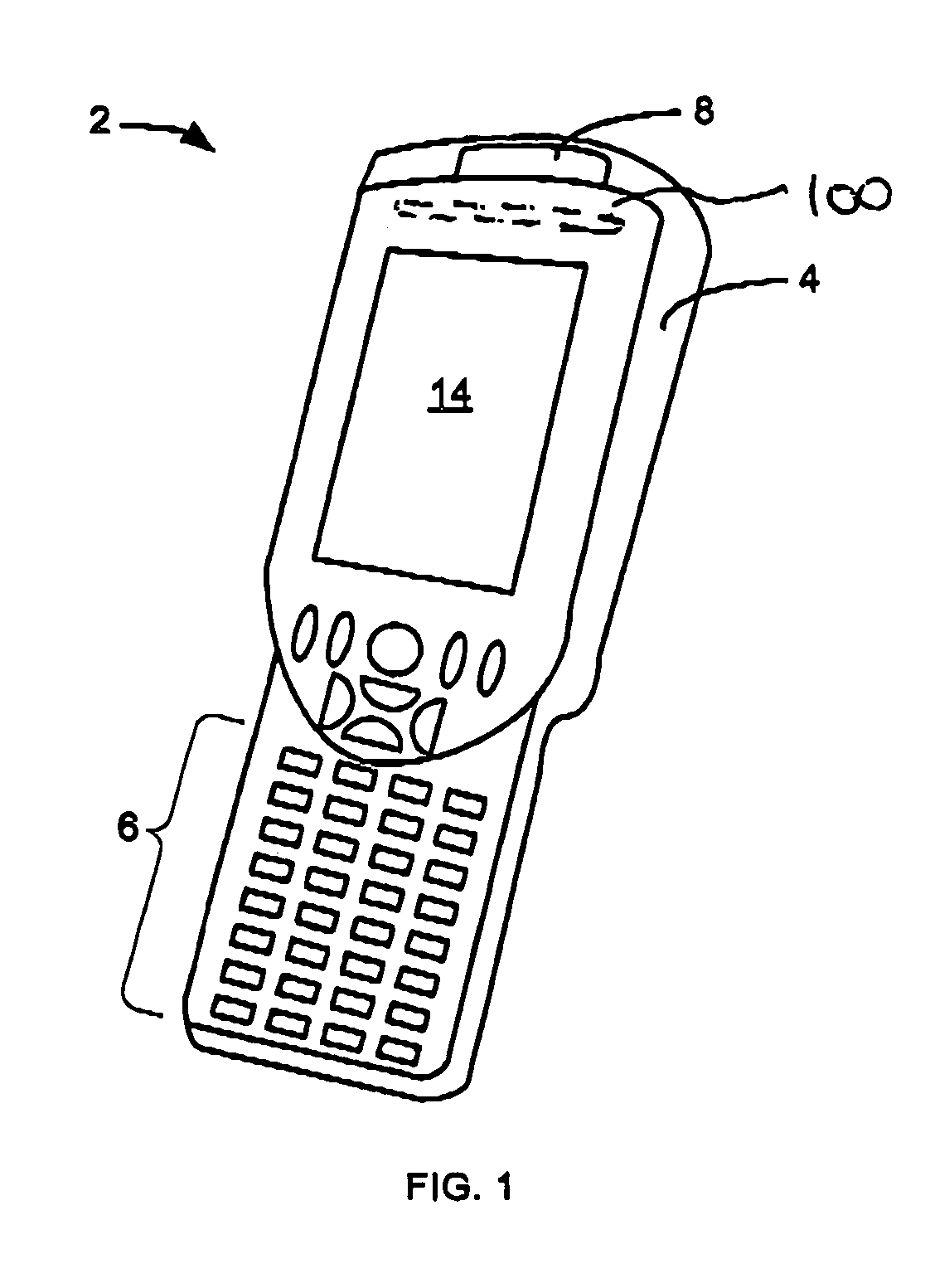
[0024]Referring to FIG. 1, there is shown a hand held scanner 2 having a body 4 and a display 14. The scanner may include an input device, such as keypad 6, and is used to read and store information from barcodes or the like through a scanner window 8. The body 4 contains control and data acquisition components as well as a communication module and an internal antenna 100. The scanner 2 maybe used in a variety of locations in which transfer of data to a central database is desirable.
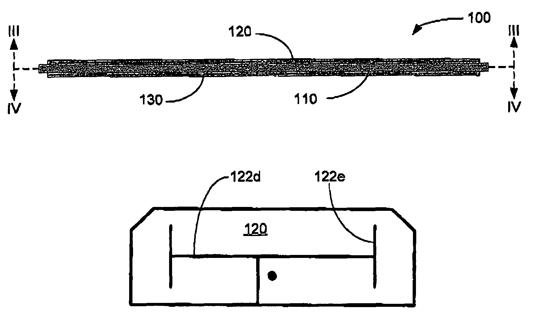
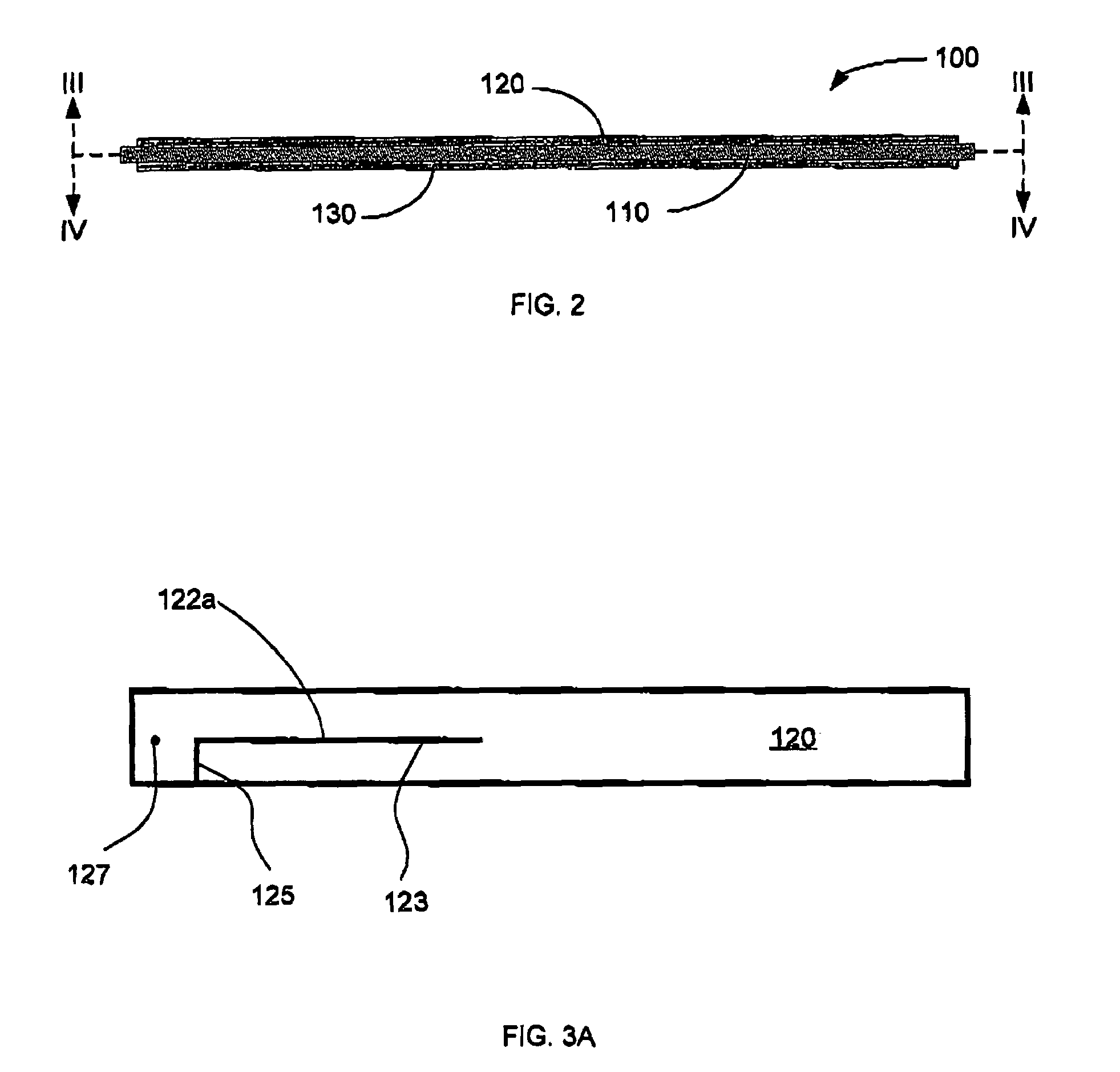
[0025]Referring therefore to FIGS. 2, 3A and 4A, the antenna 100 comprises a substrate 110 having two oppositely directed conductive planes 120 and 130. The plane 120 may be referred to as the source plane 120 while the bottom plane 130 may be referred to as the ground plane 130. Slots 122 and 132 are formed in the planes 120, 130 respectively. In a particular embodiment, the substrate 110 may be, for example, the substrate portion of a printed circuit board (PCB). The conductive planes 120, 130 are crea...
PUM
 Abstract
Description
Claims
Application Information