

Ocular lens
A technology of eyepieces and lenses, applied in the field of eyepieces, can solve the problems of unfavorable eyepiece miniaturization, long working distance, etc., and achieve the effect of high imaging quality and short working distance
- Summary
- Abstract
- Description
- Claims
- Application Information
AI Technical Summary
Problems solved by technology
Method used
Image

Examples
Embodiment 1
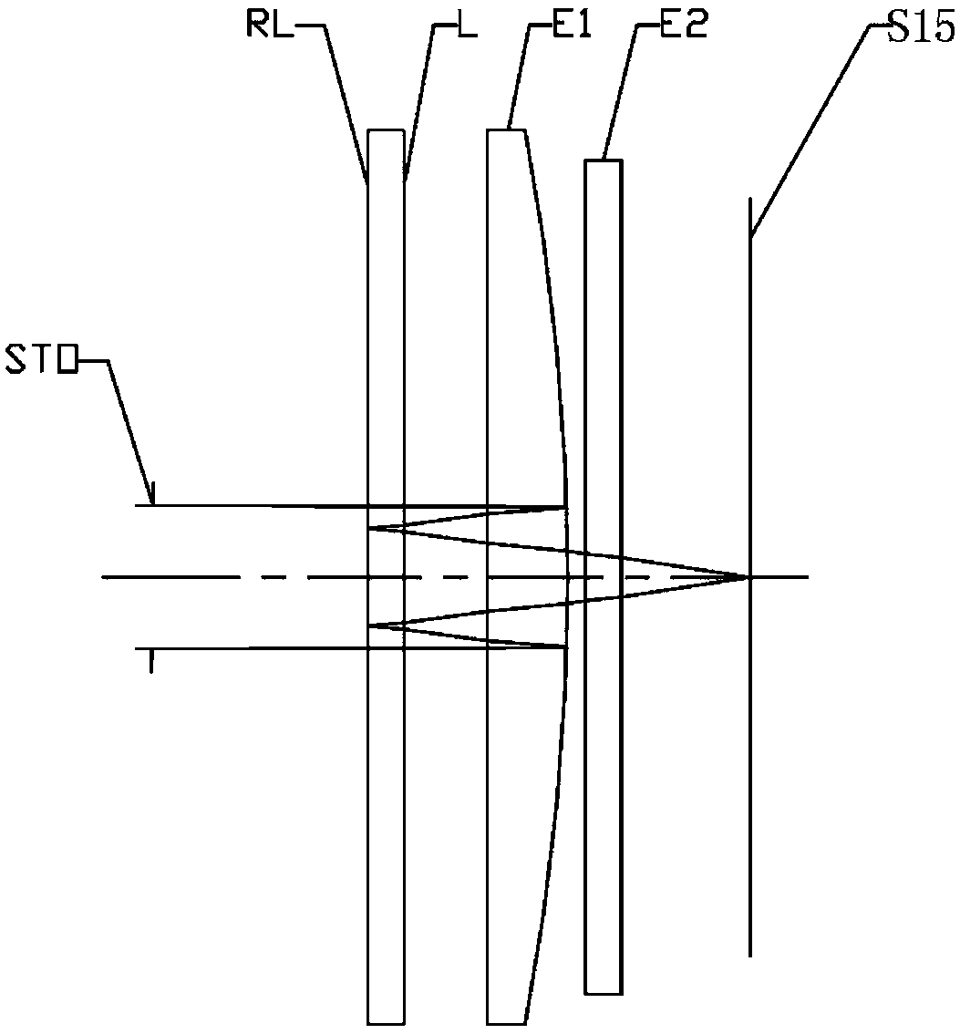
[0056] Refer to the following figure 1 with figure 2 An eyepiece according to Embodiment 1 of the present application is described. figure 1 A schematic structural view of the eyepiece according to Embodiment 1 of the present application is shown.
[0057] Such as figure 1 As shown, the eyepiece according to the exemplary embodiment of the present application includes sequentially along the optical axis from the human eye side to the image source side: a stop STO, a reflective polarizer RL, a 1 / 4 wave plate L, a first lens E1, a filter Light sheet E2 and image source surface S15.
[0058] The first lens E1 has positive refractive power, its side near the human eye is convex, and the side near the image source is convex, and the side of the first lens E1 near the human eye is a Fresnel surface, and the side near the image source is aspherical. Wherein, a layer of semi-transparent and semi-reflective optical film is coated on the side near the image source of the first lens...
Embodiment 2
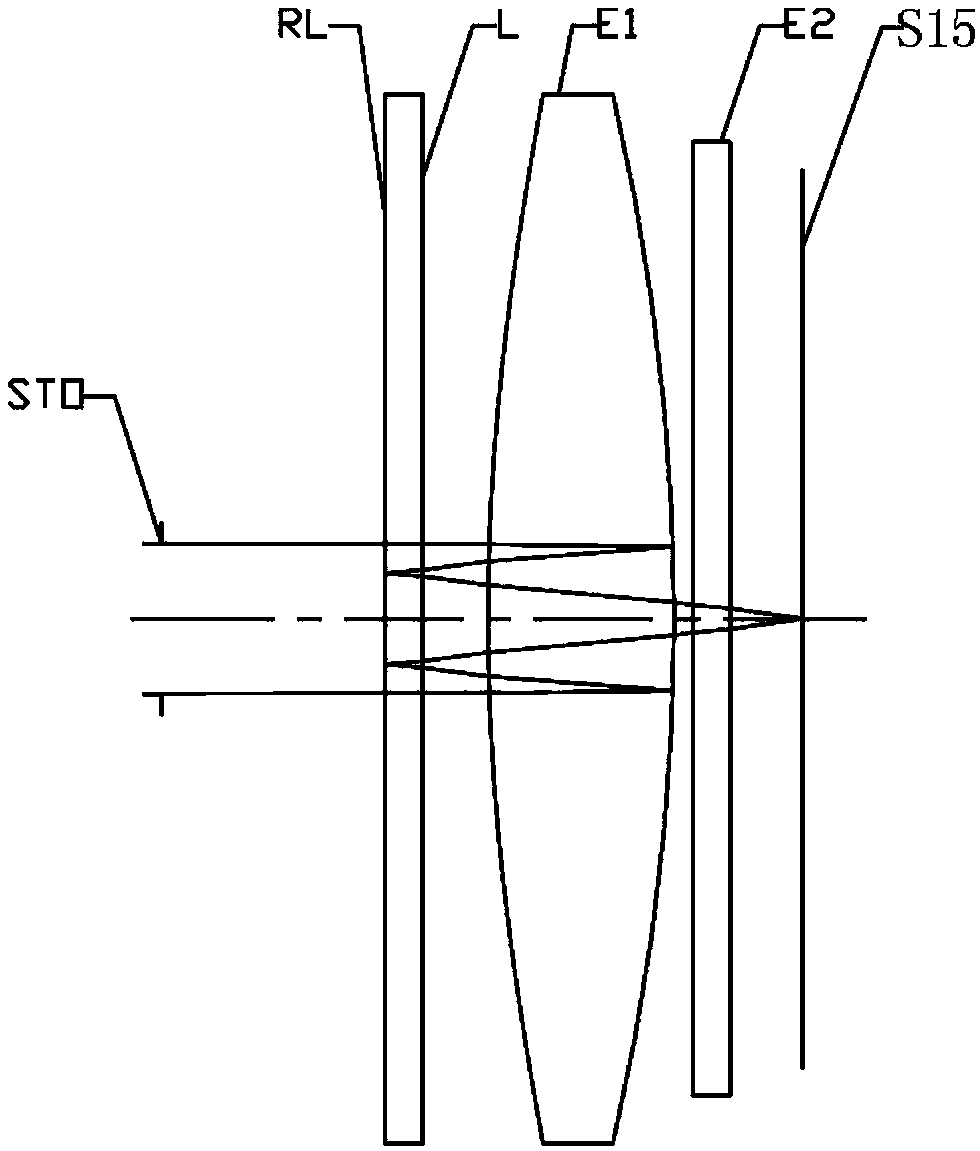
[0073] Refer to the following Figure 3 to Figure 4 An eyepiece according to Embodiment 2 of the present application will be described. In this embodiment and the following embodiments, for the sake of brevity, descriptions similar to those in Embodiment 1 will be omitted. image 3 A schematic structural view of the eyepiece according to Embodiment 2 of the present application is shown.
[0074] Such as image 3 As shown, the eyepiece according to the exemplary embodiment of the present application includes sequentially along the optical axis from the human eye side to the image source side: a stop STO, a reflective polarizer RL, a 1 / 4 wave plate L, a first lens E1, a filter Light sheet E2 and image source surface S15.
[0075] The first lens E1 has positive refractive power, its side near the human eye is convex, and its side near the image source is convex, and the first lens E1's side near the human eye and the side near the image source are both aspherical. Wherein, a la...
Embodiment 3
[0085] Refer to the following Figure 5 with Image 6 An eyepiece according to Example 3 of the present application will be described. image 3 A schematic structural view of the eyepiece according to Embodiment 3 of the present application is shown.
[0086] Such as Figure 5 As shown, the eyepiece according to the exemplary embodiment of the present application includes sequentially along the optical axis from the human eye side to the image source side: a stop STO, a reflective polarizer RL, a 1 / 4 wave plate L, a first lens E1, a filter Light sheet E2 and image source surface S15.
[0087] The first lens E1 has positive refractive power, its side near the human eye is convex, and its side near the image source is convex, and the first lens E1's side near the human eye and the side near the image source are both aspherical. Wherein, a layer of semi-transparent and semi-reflective optical film is coated on the side near the image source of the first lens E1, and the semi-...
PUM
| Property | Measurement | Unit |
|---|---|---|
| dispersion coefficient | aaaaa | aaaaa |
Abstract
Description
Claims
Application Information