Sub-scanning interval adjusting apparatus for multi-beam laser scanning unit

Inactive Publication Date: 2006-05-23
SAMSUNG ELECTRONICS CO LTD
View PDF9 Cites 24 Cited by
  • Summary
  • Abstract
  • Description
  • Claims
  • Application Information

AI Technical Summary

Benefits of technology

[0027]Accordingly, it is an aspect of the present invention to provide a sub-scanning interval adjusting apparatus of a multi-beam laser scanning unit adjusting an interval in a sub-scanning direction between two lines of laser light with ease without having deviation of starting positions of the laser light of image formation in a scanning direction.
[0035]With a sub-scanning interval adjusting apparatus for a multi-beam laser scanning unit according to the present invention, an interval between a plurality of laser beams in a sub-scanning direction can be easily adjusted without causing starting points of image formation in a scanning direction to be deviated from each other. Since there is no need to employ software or a device to compensate for the deviation of the image formation starting points, construction of the scanning unit becomes simplified, and a cost of a material is reduced.

Problems solved by technology

This way, however, has been accompanied by problems, such as an increase of noise, and also a high material cost mainly due to the requirement for a high-speed motor.
In the meantime, when components of the laser scanning unit are assembled, errors inevitably occur due to assembling status or precision of the respective components.
And this usually causes an undesired phenomenon, so-called ‘jittering’, in the laser printer with high-resolution, deteriorating a sharpness of a printing image.
However, employment of the compensation software or device causes a structure of the laser scanning unit to be complex, and a material cost increases.

Method used


Image

  • Sub-scanning interval adjusting apparatus for multi-beam laser scanning unit
  • Sub-scanning interval adjusting apparatus for multi-beam laser scanning unit
  • Sub-scanning interval adjusting apparatus for multi-beam laser scanning unit

Examples


Embodiment Construction

[0047]Reference will now be made in detail to embodiments of the present invention, examples of which are illustrated in the accompanying drawings, wherein like reference numerals refer to the like elements throughout. The embodiments are described in order to explain the present invention by referring to the figures.

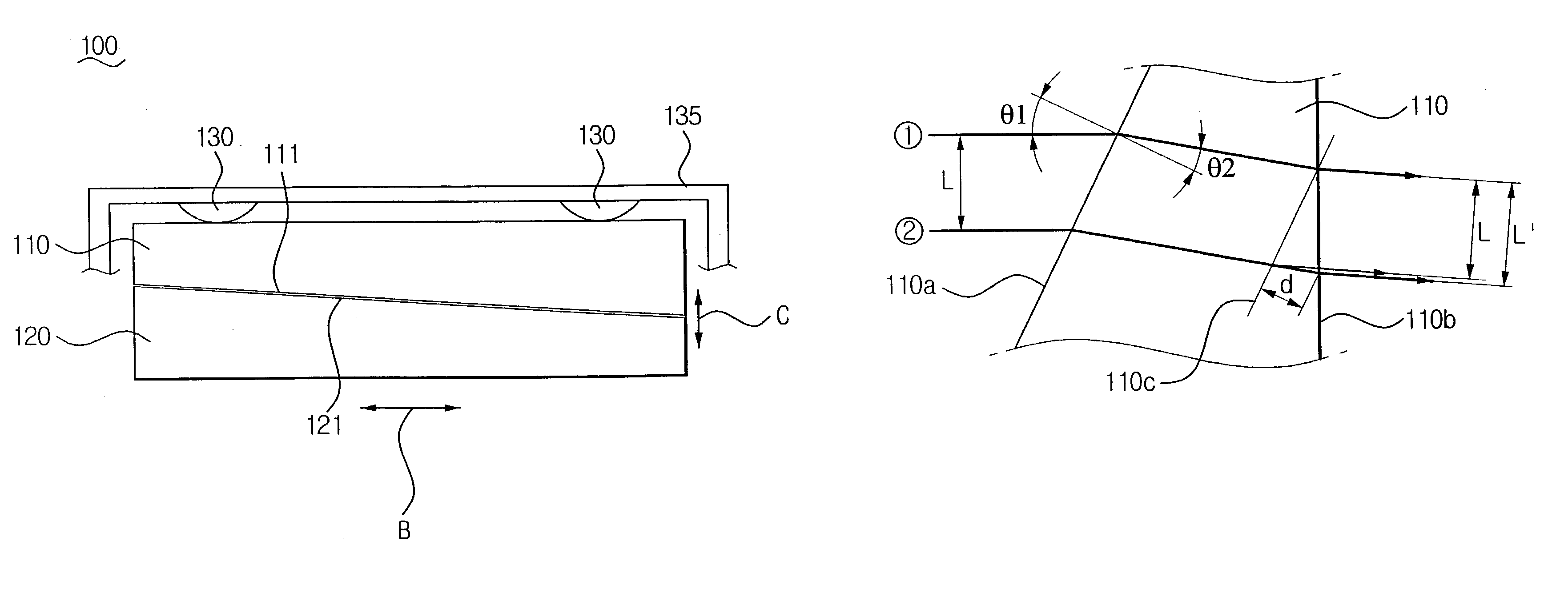
[0048]Hereinafter, the present invention will be described in detail with reference to the accompanying drawings. Referring to FIGS. 4 and 5, a sub-scanning interval adjusting apparatus 100 for a multi-beam laser scanning unit according to an embodiment of the present invention includes a transparent member 110, a movable member 120 and an elastic member 130.

[0049]The transparent member 110 is made of a material, such as glass or plastics, through which a laser beam passes. The transparent member 110 is generally formed by injection molding. The transparent member 110 has a predetermined optical refractivity, and it is possible that the refractivity is more than 1. A cr...


PUM


Abstract

A sub-scanning interval adjusting apparatus for a multi-beam laser scanning unit adjusts an interval between at least two laser lines that are formed on a photoreceptor drum without causing starting points of image formation to vary. In the multi-beam laser scanning unit simultaneously emitting at least two laser beams by using at least two laser sources, the sub-scanning interval adjusting apparatus includes a transparent member varying in thickness depending on its height, in a direction where the laser beams pass through, the transparent member having an inclined lower side with respect to a scanning direction of the laser beams, and a movable member having an inclined side corresponding to the inclined lower side of the transparent member, thereby adjusting an interval between the laser beams by moving the movable member in the scanning direction and thus varying the height of the transparent member with respect to the laser sources. An elastic member is formed on the transparent member to press the transparent member with respect to the movable member. The transparent member is formed to have a shape of a triangle or a trapezoid in cross-section in the direction where the laser beams pass through. The transparent member has a refractivity greater than 1.

Description

CROSS-REFERENCE TO RELATED APPLICATIONS[0001]This application claims the benefit of Korean Patent Application No. 2002-49961, filed Aug. 23, 2002, in the Korean Intellectual Property Office, the disclosure of which is incorporated herein by reference.BACKGROUND OF THE INVENTION[0002]1. Field of the Invention[0003]The present invention generally relates to a multi-beam laser scanning unit used in an image forming apparatus, such as a laser printer, and more particularly, to a sub-scanning interval adjusting apparatus of a multi-beam laser scanning unit adjusting a distance between at least two beams of the multi-beam laser scanning unit.[0004]2. Description of the Related Art[0005]Generally, a laser printer forms an image by processes of processes of focusing a laser beam from a laser scanning unit onto a photoreceptor drum in accordance with a video signal, developing an electrostatic latent image on the photoreceptor drum, and transferring the developed image onto a printing medium...

Claims


Application Information

Patent Timeline
IPC IPC(8): B41J27/00B41J2/47G02B26/10G02B26/12
CPCG02B26/123B41J2/473G02B26/10
Inventor YOO, JAE-HWAN
Owner SAMSUNG ELECTRONICS CO LTD
Why Eureka
Try Eureka