Negative pressure type rotary head drum unit and magnetic tape drive using the same

Inactive Publication Date: 2006-05-23
SONY CORP
View PDF4 Cites 5 Cited by
  • Summary
  • Abstract
  • Description
  • Claims
  • Application Information

AI Technical Summary

Benefits of technology

[0033]It is accordingly an object of the present invention to provide a rotary head drum unit that can prevent an increase in contact pressure of a magnetic tape sliding on a tape sli

Problems solved by technology

However, the tape sliding surface i of each magnetic head e has a size of 1 mm×100 μm, for example, so that it is not necessarily easy to form the tape sliding surface i into a curved surface.
Accordingly, in the case that the shape of the tape sliding surface i is designed to accommodate the high-stiffness tape j, there arises a problem that the low-stiffness tape k does not come into contact with the tape sliding surface i (see FIG. 25), and the contact of the magnetic tape h and each magnetic head e becomes non-uniform, causing a reduction and variations in recording or reproduction output.
For the above reasons, the contact (contact condition) between each magnetic head e and the magnetic tape h in the in

Method used


Image

  • Negative pressure type rotary head drum unit and magnetic tape drive using the same
  • Negative pressure type rotary head drum unit and magnetic tape drive using the same
  • Negative pressure type rotary head drum unit and magnetic tape drive using the same

Examples


Embodiment Construction

[0065]Some preferred embodiments of the present invention will now be described in detail with reference to the attached drawings.

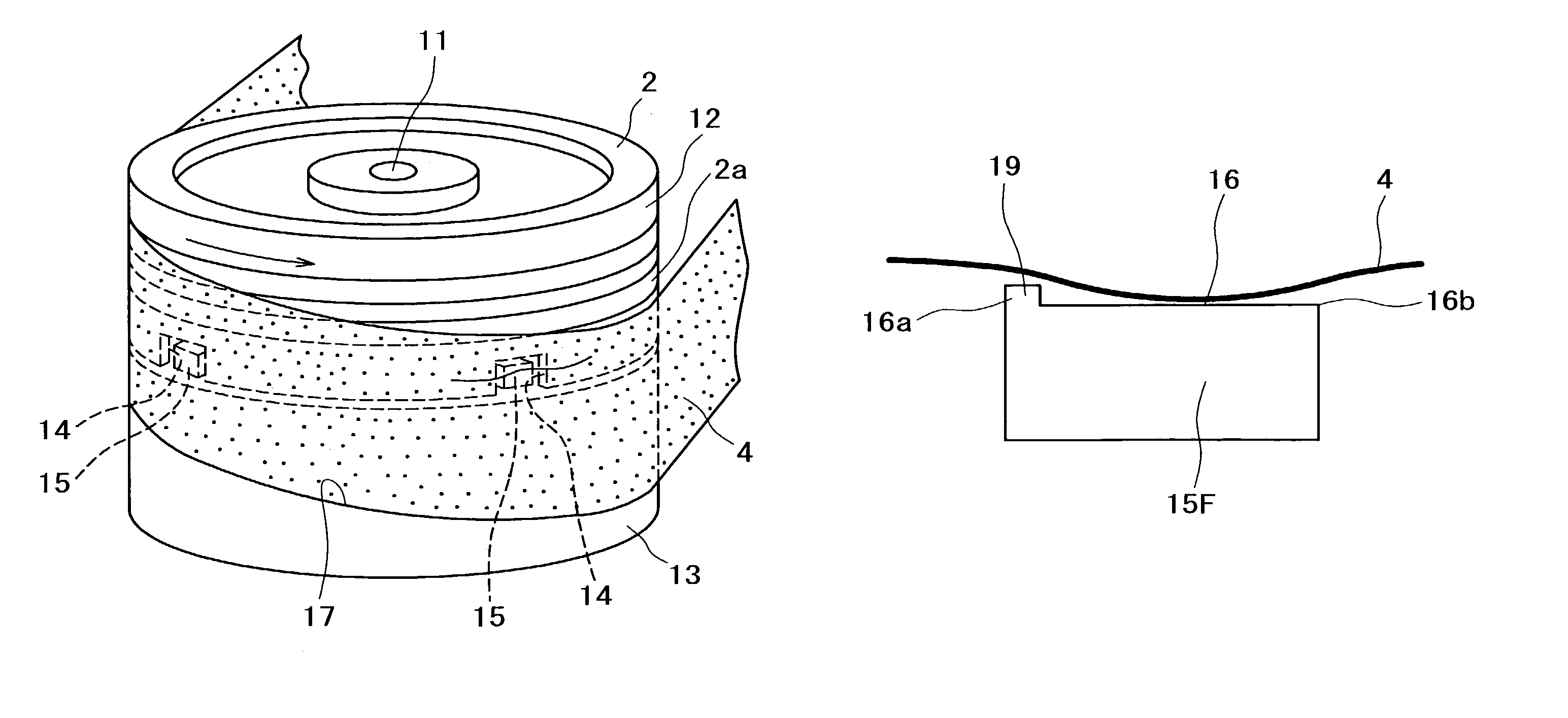
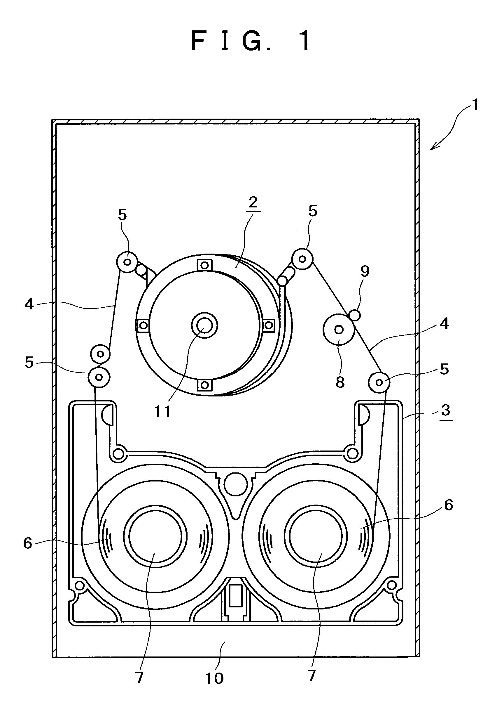
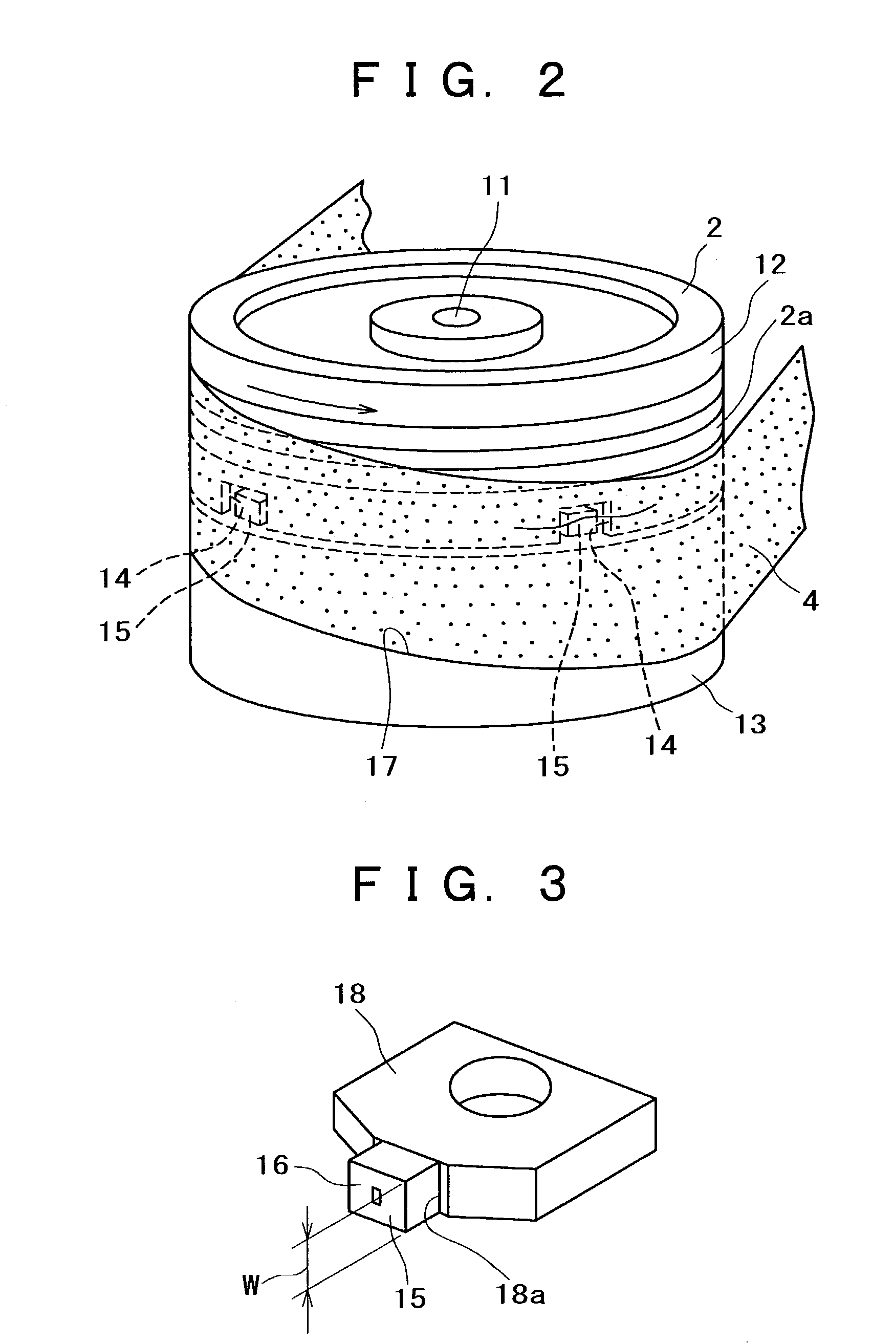
[0066]Referring first to FIG. 1, there is shown a magnetic tape drive 1 according to a preferred embodiment of the present invention. The magnetic tape drive 1 includes a rotary head drum unit 2, a plurality of guide pins 5 for drawing a magnetic tape 4 out of a tape cassette 3 and wrapping the drawn magnetic tape 4 around the rotary head drum unit 2 to form a given tape path, a pair of reel supports 7 for supporting a pair of reels 6 accommodated in the tape cassette 3, a pinch roller 8, and a capstan shaft 9 for running the magnetic tape 4 in cooperation with the pinch roller 8.

[0067]Reference numeral 10 denotes a chassis of the magnetic tape drive 1. The rotary head drum unit 2 is arranged so that its axis is slightly inclined with respect to the chassis 10. When the tape cassette 3 is loaded into a cassette loading portion of the magnetic tape drive 1...


PUM


Abstract

Disclosed herein is a rotary head drum unit including a cylindrical drum surface and a magnetic head for recording/reproducing a signal to/from a magnetic tape running along the drum surface. The magnetic head has a tape sliding surface adapted to come into sliding contact with the magnetic tape. The tape sliding surface of the magnetic head is positioned at a level lower than the height of the magnetic tape flying above the drum surface. The magnetic tape is brought into contact with the tape sliding surface by negative pressure. With this configuration, an increase in contact pressure of the magnetic tape sliding on the tape sliding surface of the magnetic head can be prevented and the contact pressure can be uniformed to thereby prevent a reduction and variations in magnetic recording or reproduction output.

Description

RELATED APPLICATION DATA[0001]The present application claims priority to Japanese Application(s) No(s). P2002-041373 filed Feb. 19, 2002, which application(s) is / are incorporated herein by reference to the extent permitted by law.BACKGROUND OF THE INVENTION[0002]The present invention relates to a rotary head drum unit and a magnetic tape drive, and more particularly to a technique for improving a contact condition between a magnetic head and a magnetic tape.[0003]A rotary head drum unit is used to record a signal to a magnetic tape such as a tape-like magnetic recording medium or reproduce a signal recorded on the magnetic tape. Such a rotary head drum unit is mounted in a video tape recorder, for example, and this unit is composed of a fixed drum and a rotating drum. The rotating drum is provided with a magnetic head, so that when the rotating drum is rotated in one direction, the magnetic head comes into sliding contact with the magnetic tape to thereby record or reproduce a signa...

Claims


Application Information

Patent Timeline
IPC IPC(8): G11B5/52G11B5/53G11B15/61
CPCG11B5/534
Inventor KONDO, MASAYUKIOZUE, TADASHI
Owner SONY CORP
Why Eureka
Try Eureka