Motor controller incorporating an electronic circuit for protection against inrush currents

a motor controller and electronic circuit technology, applied in the field of electronic circuits, can solve the problems of generating conductor transmitted radio noise, rfi filter designer facing another, fault current circuit breaker activation, etc., to achieve the effect of enhancing the noise attenuation effect of the noise-decoupling capacitor, reducing the effective resistance of the resistor network, and reducing the component cos

Inactive Publication Date: 2006-05-23
DANFOSS DRIVES
View PDF15 Cites 130 Cited by
  • Summary
  • Abstract
  • Description
  • Claims
  • Application Information

AI Technical Summary

Benefits of technology

[0012]By designing a passive protection circuit as described, it is possible to minimise the number of electronic components required to make a circuit combining noise filter and inrush protection. The circuit protects both the intermediate capacitor and the noise-decoupling capacitor against excessive inrush currents, and simultaneously functions as a noise filter during both start up and normal operation. When the switch is open, the resistor network has one effective resistance towards inrush and noise currents, whereas upon closure of the switch, the network has a different effective resistance. The network exhibits differing resistance dependent upon whether the current is common mode current or differential current.
[0022]To achieve the best possible attenuation of cable-transmitted radio noise, noise should be filtered on both the mains side and in the intermediate circuit. Noise filtering on the mains side is achieved by connecting a minimum of two capacitors in series from the supply cable to earth. The first capacitor, which is connected to earth, is coupled in parallel with a switch that is held open during inrush. In this way the first capacitor functions as inrush protection. If desired, a resistor can be connected in parallel with the switch, and with the first capacitor. By having filter and inrush protection on the mains side and in the intermediate circuit, a two-stage noise filter is achieved. The same controller can conveniently activate the switches simultaneously.

Problems solved by technology

A side effect of this modulation is the generation of conductor transmitted radio noise.
However, the use of RFI filters causes problems when at the same time a fault current circuit breaker is installed on the mains side of the frequency converter.
RFI filters installed in the intermediate circuit can also cause activation of the fault current circuit breaker.
The RFI filter designer faces another problem, namely the use of symmetrically and asymmetrically earthed mains supplies.
Frequency converters on asymmetric mains supplies can cause considerable earth leakage currents, and will trigger a fault current circuit breaker more often than frequency converters connected to symmetric mains supplies.
As previously mentioned, the noise-decoupling capacitors in the RFI filters cause inrush currents to earth.
Because the resistance is very low during start up, the capacitor connected to the negative conductor can be regarded as short-circuited, thus limiting the charging current.
However, SU 1658344 does not describe the problems associated with the use of fault current circuit breakers in combination with frequency converters, and the PTC solution used in SU 1658344 will most probably result in such a large flow of current to earth, that the undesired triggering of a fault current circuit breaker will occur.
However, a disadvantage of the circuit is the requirement for two relays.
The physical dimensions of these relays are large, which is undesirable since the tendency for frequency converters is towards ever-smaller motor controllers.

Method used


Image

  • Motor controller incorporating an electronic circuit for protection against inrush currents
  • Motor controller incorporating an electronic circuit for protection against inrush currents
  • Motor controller incorporating an electronic circuit for protection against inrush currents

Examples


Embodiment Construction

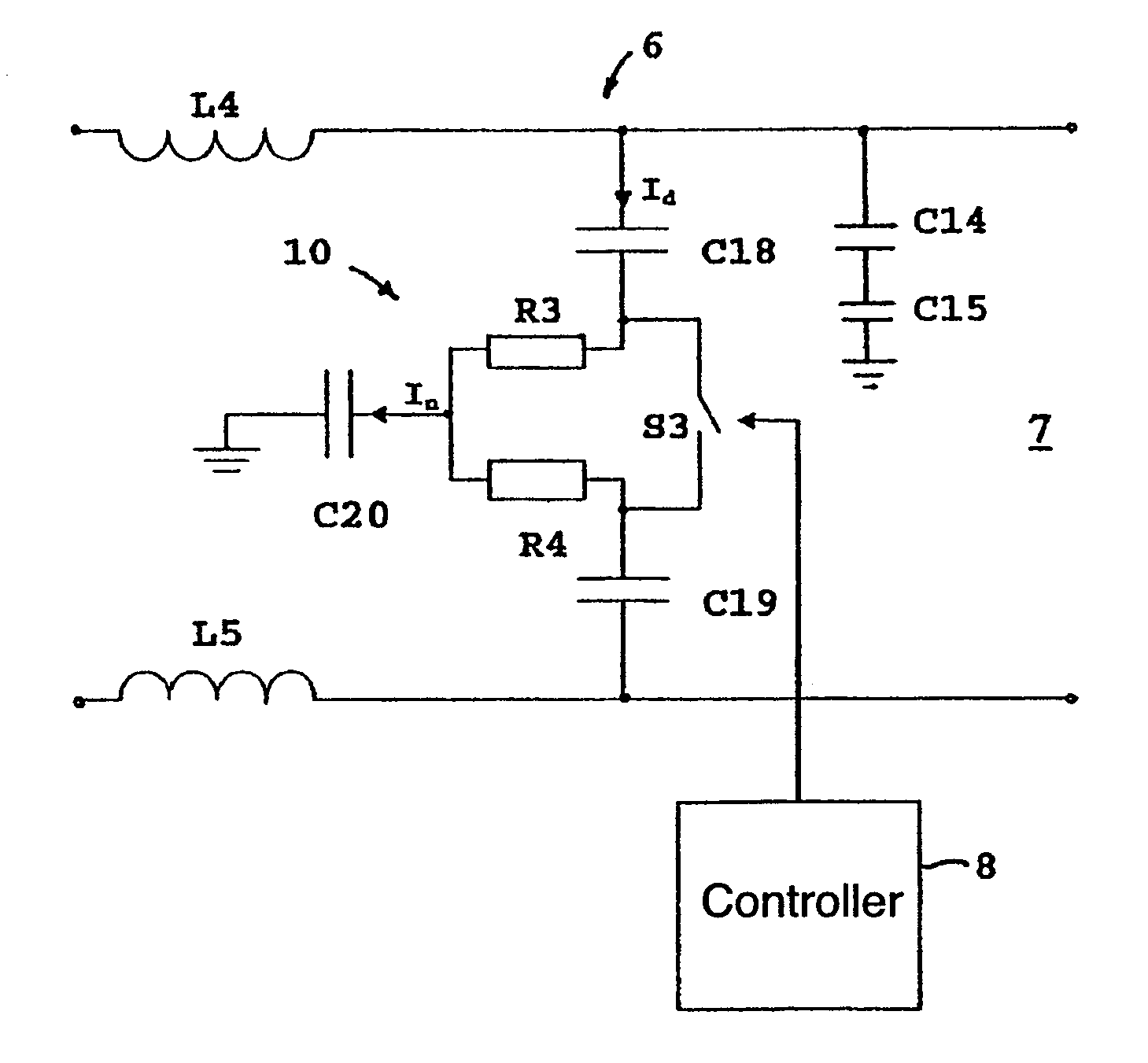
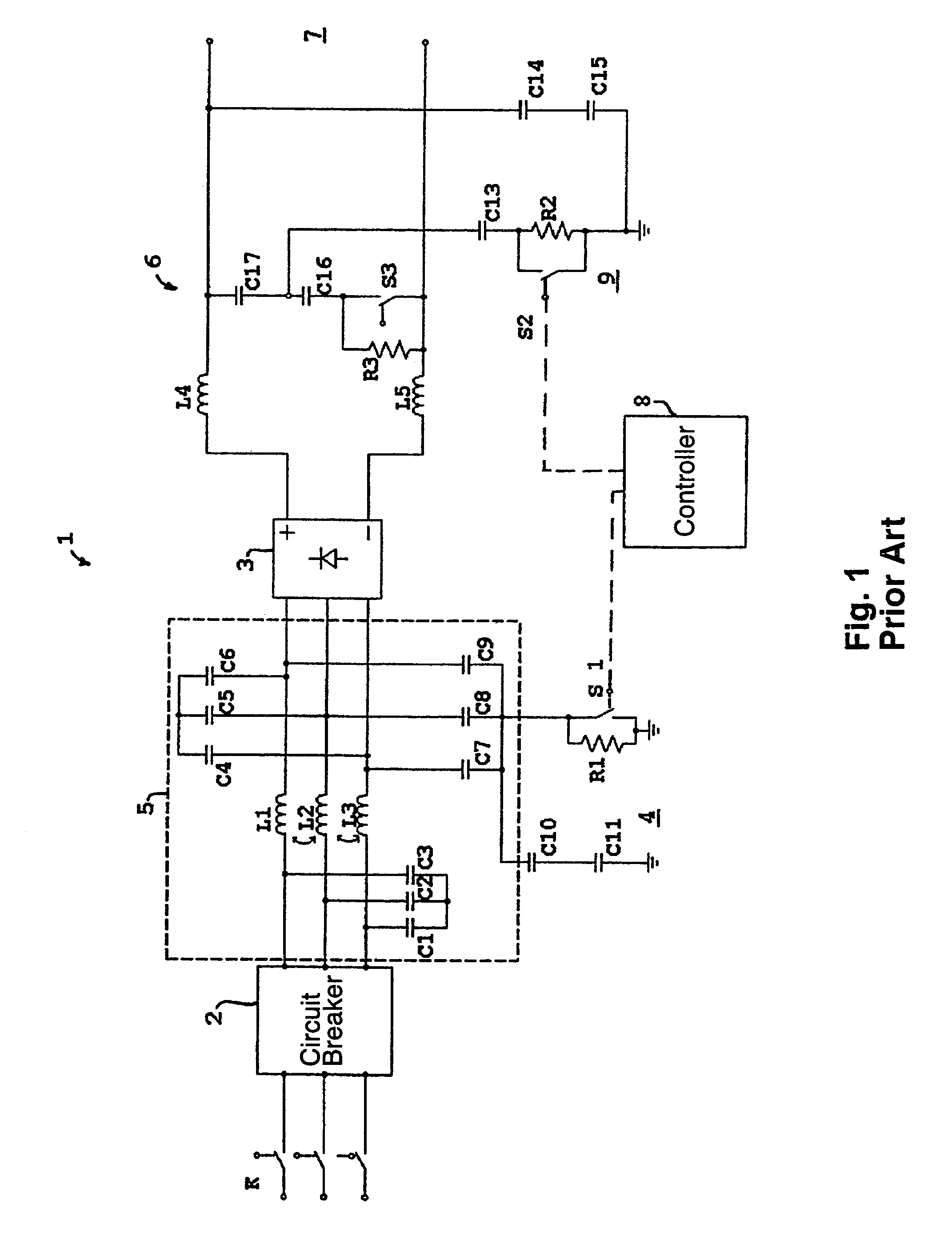
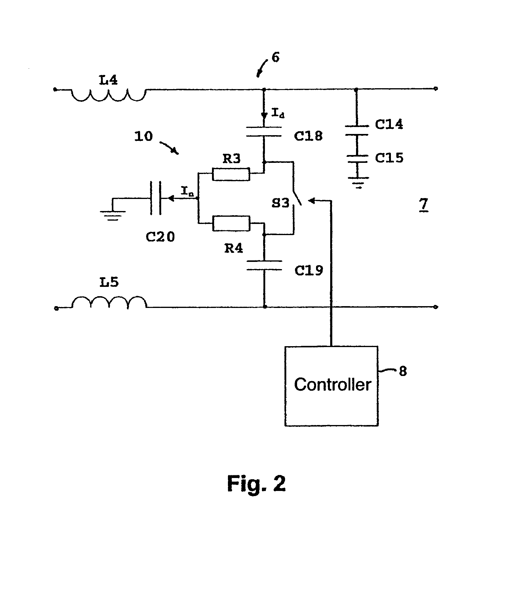
[0027]FIG. 1 shows a circuit for inrush protection and noise filtration as described in the applicant's patent application PA 2000 01837. Reference number 1 indicates the mains section and the input section of a frequency converter. On the mains side, a voltage source (not illustrated) is connected to the switches K, which are then connected to a fault current circuit breaker 2, through which three phases pass to the input of the frequency converter. The capacitors C1, C2 and C3 are connected to the phase conductors at one pole, and at the other pole they are connected in a common star point. They function in a conventional manner to attenuate differential noise. Capacitors C4, C5 and C6 have the same role. On each phase between the two sets of capacitors, a coil (L1, L2 and L3) is positioned, functioning as a common mode coil. These three coils are wound on a common ferrite core. The capacitors C7, C8 and C9 branch out from the supply conductors, and function as noise-decoupling ca...


PUM


Abstract

Inrush currents in the dc intermediate circuit of a motor controller necessitate the incorporation of protection circuits. These circuits usually take the form of a resistor inserted in series with the intermediate circuit, and the resistor is short-circuited after completion of inrush by a switch positioned in parallel with the resistor. To reduce cable-transmitted electrical noise an earthed noise-decoupling capacitor is added to the intermediate circuit, but it also requires protection against inrush currents. To minimise the number of components, a protection circuit is described which combines noise filtration and inrush protection. According to the invention, the inrush resistor has the form of a resistor network and is connected to a switch which via a controller alters the resistance of the resistor network, so that when the switch is open, the resistance to a differential current is greater than the resistance to a common mode current, and when the switch is closed, there is greater resistance to a common mode current than to the differential current.

Description

CROSS-REFERENCE TO RELATED APPLICATIONS[0001]This application is entitled to the benefit of and incorporates by reference essential subject matter disclosed in Danish Patent Application No. PA 2002 00786 filed on May 22, 2002.FIELD OF THE INVENTION[0002]The invention relates to an electronic circuit, which is installed as protection in a dc intermediate circuit in a motor controller such as a frequency converter, where protective measures are required due to large starting currents in the intermediate circuit. Protection is especially applicable to the intermediate capacitor, but the noise-decoupling capacitors used in RFI (Radio Frequency Interference) filters can also be damaged during the start up sequence.BACKGROUND OF THE INVENTION[0003]In frequency converters for speed regulation of electric motors, pulse width and pulse amplitude modulation of power semiconductors is extensively used. A side effect of this modulation is the generation of conductor transmitted radio noise. The...

Claims


Application Information

Patent Timeline
Patent Type & Authority Patents(United States)
IPC IPC(8): H02H7/08H02H3/33H02H9/00H02M7/06
CPCH02M7/062H02H9/001H02H3/337H02H9/005
Inventor POULSEN, JOERN
Owner DANFOSS DRIVES
Why Eureka
Try Eureka