X-ray tube with liquid-metal fluid bearing

a technology of liquid metal and bearing, applied in the field of x-ray tubes, can solve the problems of high angular acceleration and other problems, and achieve the effects of good cooling, efficient bearing of rotating anodes, and simple means

Inactive Publication Date: 2006-05-23
SIEMENS AG
View PDF6 Cites 21 Cited by
  • Summary
  • Abstract
  • Description
  • Claims
  • Application Information

AI Technical Summary

Benefits of technology

[0009]An object of the present invention is to provide an x-ray tube having a basic structure as initially described, wher

Problems solved by technology

Bearing requirements for such a rotating anode are significant because the anode is frequently operated with

Method used


Image

  • X-ray tube with liquid-metal fluid bearing
  • X-ray tube with liquid-metal fluid bearing

Examples


Embodiment Construction

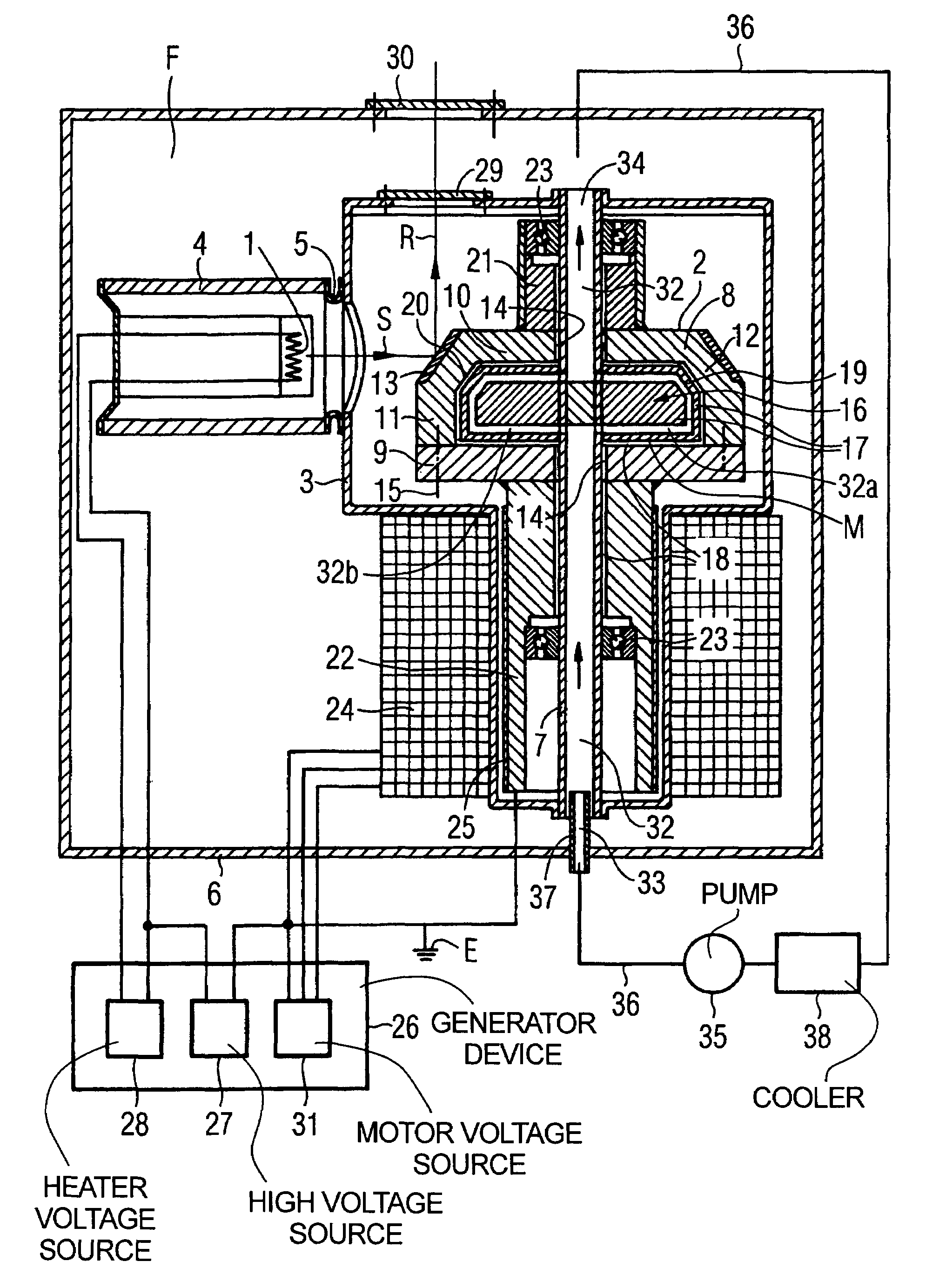
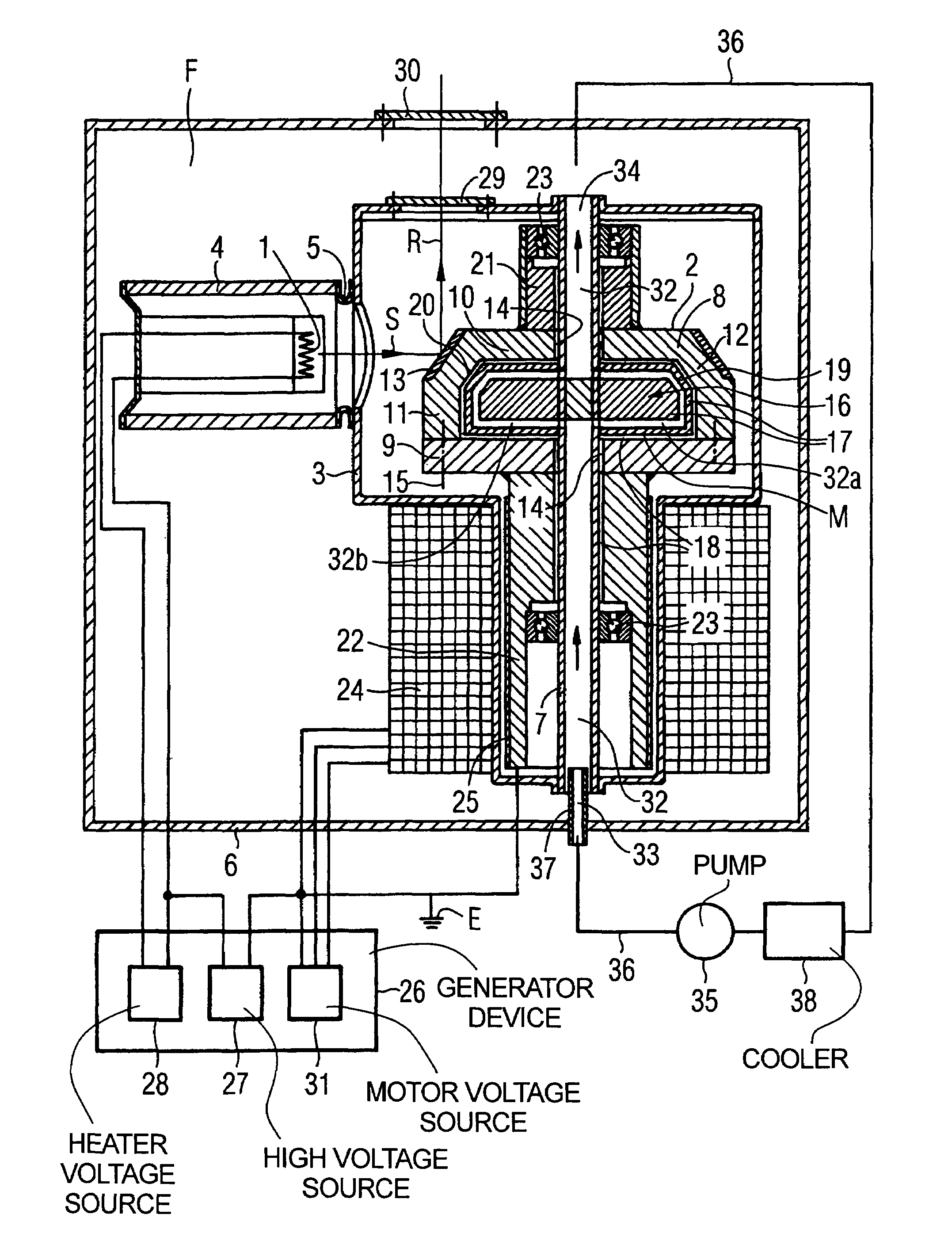
[0019]The x-ray tube shown in the FIGURE has a stationary cathode 1 and a rotating anode 2. The rotating anode 2 is disposed in a stationary vacuum housing 3. The cathode 1 is disposed in an isolator housing 4 that is vacuum-sealed to the vacuum housing 3 by means of a metal ring 5. The vacuum housing 3 is disposed in a protective housing 6 that is filled with an electrically insulating liquid F, for example insulating oil.

[0020]A housing-fixed axle 7 extends completely through the vacuum housing 3, on which the rotating anode 2 is mounted such that it can rotate. The axle 7 is vacuum-sealed at both ends by the wall of the vacuum housing 3.

[0021]The rotating anode 2 is rotationally symmetric with regard to the axle 7. It has a tank-like or shell-like first part that is subsequently designated as a tank 8. The tank 8 is terminated on an open side thereof by a flat, radially aligned second part that is subsequently designated as a cover 9. The tank 8 has a radially aligned base 10, a ...


PUM


Abstract

An x-ray tube has a stationary cathode and a rotating anode in a vacuum housing. The anode is positioned on a housing-fixed axle such that it can be rotated, and is fashioned as a hollow body in the interior of which an axle-fixed ring projection is disposed, such that, at least between an inner surface of the rotating anode and the adjacent outer surface of the ring projection, a gap exists that is filled with liquid metal and forms a liquid-metal fluid bearing for the rotating anode.

Description

BACKGROUND OF THE INVENTION[0001]1. Field of the Invention[0002]The present invention concerns an x-ray tube of the type having a stationary cathode and a rotating anode in a vacuum housing, the anode being positioned on a housing-fixed axle such that it can be rotated, and the rotating anode being formed as a hollow body with an interior an axle-fixed ring projection is disposed.[0003]2. Description of the Prior Art[0004]X-ray radiation conventionally is generated by bombarding an anode with an electron beam originating from a cathode. The cathode and the anode are arranged in a vacuum housing. The anode typically is a rotating anode that rotates under the incident electron beam in order to prevent the focal spot from being stationary with respect to the anode. The focal spot, meaning the point at which the electron beam strikes the anode surface, moves (when viewed in the context of a coordinate system rotating with the rotating anode) along a circular path over the anode surface....

Claims


Application Information

Patent Timeline
IPC IPC(8): H01J35/26H01J35/10H01J35/24H01J35/28
CPCH01J35/10H01J2235/1086
Inventor BITTL, HERBERT
Owner SIEMENS AG
Why Eureka
Try Eureka