Triaxial tension compression, shear testing apparatus

a technology of shear testing and compression, applied in the direction of tension measurement, force/torque/work measurement, instruments, etc., can solve the problems of complex responses, unrefined structure technology, and difficult to analyze reliable structures, etc., to facilitate triaxial testing, easy to assemble and disassemble, and cost-effective

Inactive Publication Date: 2006-05-30
THE UNITED STATES OF AMERICA AS REPRESENTED BY THE SECRETARY OF THE NAVY
View PDF16 Cites 48 Cited by
  • Summary
  • Abstract
  • Description
  • Claims
  • Application Information

AI Technical Summary

Benefits of technology

[0014]The present invention is directed to a material properties testing system that satisfies the need for a need for a system capable of applying combined in-plane shear and multi axial loads to a test specimen. The present invention is further directed to providing a single material testing system that is compact, cost-effective and easy to assemble and disassemble. The apparatus of the present system includes a triaxial test specimen that is configured to facilitate the triaxial testing of solid and composite specimens.
[0016]A further object of the present invention single material testing apparatus that is compact, cost-effective and easy to assemble and disassemble.
[0017]Another object of the present invention is to provide test specimens that are configured to accurately and conveniently test the material properties of solid and composite specimens by a triaxial testing apparatus.
[0023]An aspect of the apparatus of the present invention is that the test specimen further includes a plurality of rigid plates, where each plate is disposed over one of the horizontal ends for spatially stabilizing specimens made of composite materials.
[0038]The triaxial testing apparatus of the present invention enables a user to test the material properties of a triaxial test specimen by applying combined in-plane shear and multi-axial loads to the test specimen. In particular, the triaxial test apparatus is configured to expediently transfer forces from a conventional testing machine to a test specimen in the form of horizontal compression, horizontal tension, vertical compression, vertical tension and shear loads, and combinations thereof. The ends of the test specimen of the present invention are adapted for clamping by the horizontal and vertical clamping assemblies. Alternatively, the ends test specimen of the present invention may include rigid plates, where each plate is disposed over one of the horizontal ends of the test specimen for spatially stabilizing specimens made of composite materials during operation of the triaxial testing apparatus. The test specimens may also include load measurement devices that facilitate convenient and accurate measurement of the horizontal, vertical and shear loads imparted to the test specimen by the testing machine during operation of the triaxial testing apparatus.

Problems solved by technology

Although, such structures are well known in the art, the technology for the structures has not been refined such that reliable structures can be analytically designed.
Presently, modeling the mechanical properties of woven fabrics results in complex responses because of the complex microstructures of the composite materials used.
While biaxial testing apparatuses with compression and tension loading or in-plane shear testing apparatuses exist in the prior art, there are no apparatuses that exist with a combined feature of multi-plane shear and triaxial testing capabilities.
An apparent disadvantage is the need for two or more loading devices and the associated high cost of equipment.
A restrictive disadvantage of the apparatus is the requirement of the cylindrical shape of the specimen and a high cost associated with pressurization of the cylinder.
Additionally, the disadvantages include restriction to orthogonal loads about the axial, hoop and radial directions and an apparatus that is not capable of applying an in-plane shear stress to the specimen.
(U.S. Pat. No. 5,144,844) describes a cruciform planar specimen for biaxial material testing which has the disadvantage of being limited to use in two loading directions.
The apparatus also has no capability for applying an in-plane shear load to the specimen.
A disadvantage of this apparatus is that it is not capable of applying in-plane shear to the test specimen.
Another disadvantage of this apparatus is that the biaxial loading is limited to an orthogonal configuration.

Method used


Image

  • Triaxial tension compression, shear testing apparatus
  • Triaxial tension compression, shear testing apparatus
  • Triaxial tension compression, shear testing apparatus

Examples


Embodiment Construction

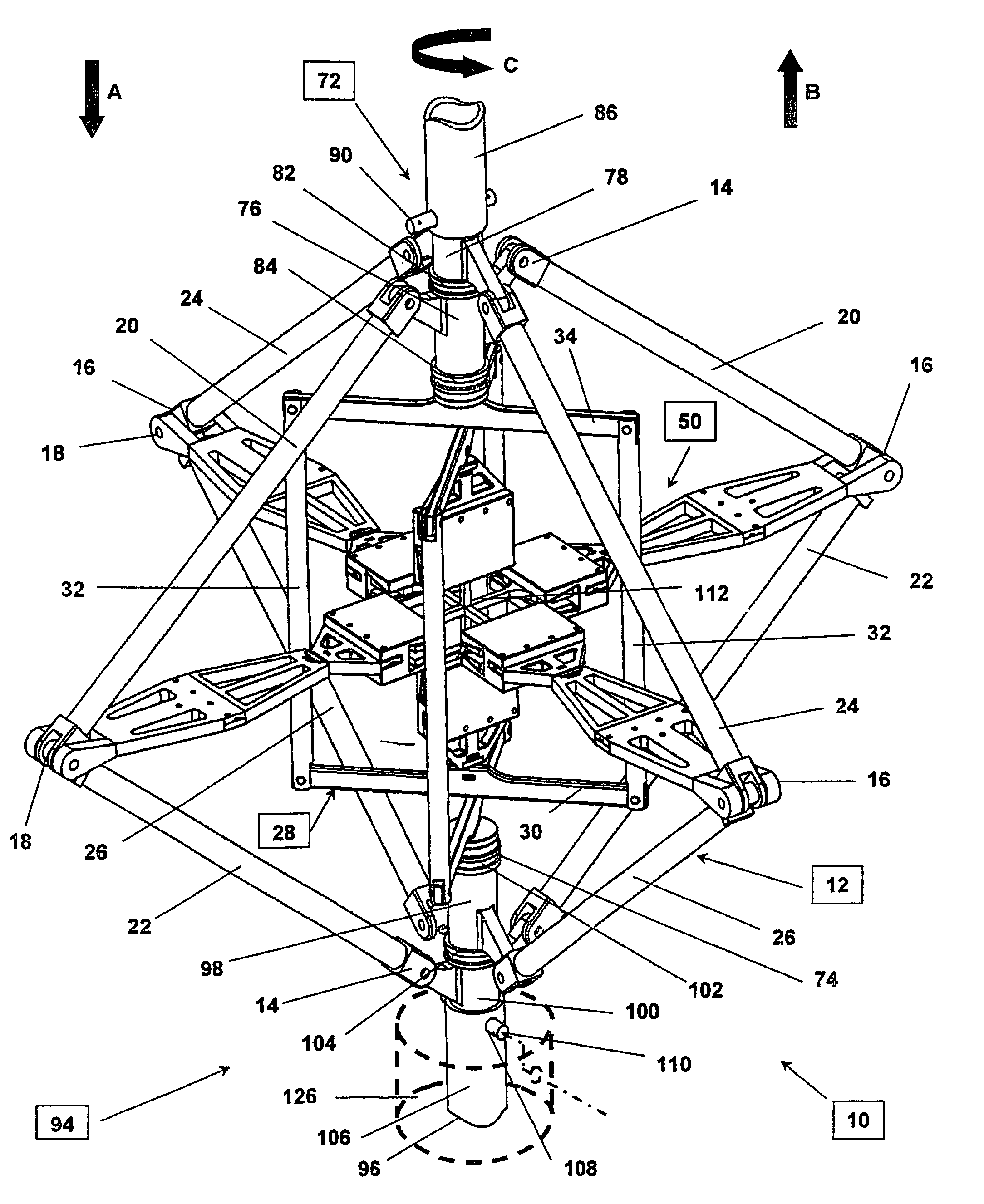
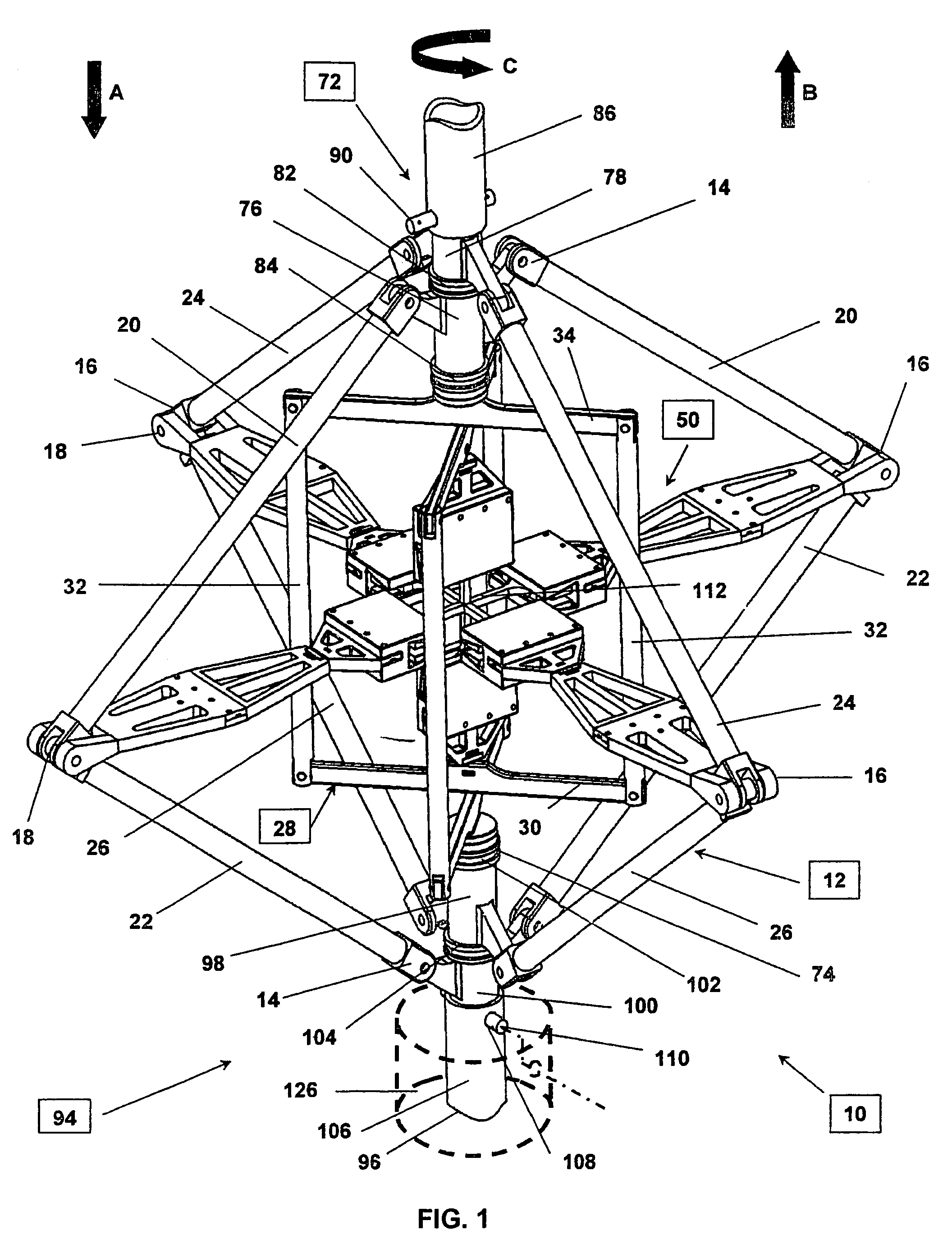
[0049]Referring now to Figures (FIGS.) 1–9, wherein like numerals refer to like elements throughout the several views, a triaxial testing apparatus 10 is shown in which the triaxial testing apparatus comprises a plurality of horizontal force members 12 and a vertical loading assembly 28 connected together to top joint assembly 72 and to bottom joint assembly 94. The horizontal force members 12, comprising linkages 20, 22, 24 and 26, are further connected to horizontal loading assembly 50 and to horizontal clamping assembly 64; and are similarly attached to vertical loading assembly 28 and to vertical clamping assembly 38. The horizontal clamping assembly 64 and the vertical clamping assembly 38 function together to rigidly clamp triaxial test specimen 112 in place for material properties testing during operation of the triaxial testing apparatus 10.

[0050]The top joint assembly 72 includes first and second sleeves 76, 78, and the bottom joint assembly 94 includes third and fourth sle...


PUM

PropertyMeasurementUnit
material propertiesaaaaaaaaaa
horizontal forceaaaaaaaaaa
rotational and linear movementaaaaaaaaaa

Abstract

A triaxial testing system of material properties having top and bottom joint assemblies that rotate about and move along a longitudinal axis in response to forces imparted by a testing machine. The joint assemblies are connected together by horizontal and vertical linkage assemblies. The horizontal and vertical linkage assemblies are connected to horizontal and vertical loading and clamping assemblies to thereby transfer in-plane and multi-axial loads from the testing machine and the joint assemblies to a material test specimen. The test specimen is rigidly clamped to the horizontal and vertical clamping assemblies. The bases and ends of the test specimen are shaped for clamping and axial loading. Rigid plates may be disposed over ends of composite test specimens for spatially stabilizing such specimens during testing. The test specimens may include devices to measure and record the axial and shear loads, displacement and strains imparted to the specimens during testing.

Description

CROSS-REFERENCE TO RELATED APPLICATIONS[0001]This application is a continuation-in-part of and claims the benefit of U.S. patent application (Ser. No. 10 / 851,748—filed on May 24, 2004 now U.S. Pat. No. 6,860,156 and allowed on Oct. 20, 2004), entitled “Combined In-Plane Shear and Multi-Axial Tension or Compression Testing”.STATEMENT REGARDING FEDERALLY SPONSERED RESEARCH OR DEVELOPMENT[0002]The invention described herein may be manufactured and used by and for the Government of the United States of America for governmental purposes without the payment of any royalties thereon or therefore.(1) FIELD OF THE INVENTION[0003]The present invention relates to a system for testing the material properties of physical specimens, more particularly to an apparatus and process for determining the mechanical properties of metals, plastics, woods, fabrics, elastomers and composites of similar materials in response to multi-axial and shear loads imparted to test specimens of such materials by the a...

Claims


Application Information

Patent Timeline
Patent Type & Authority Patents(United States)
IPC IPC(8): G01D7/00G01N3/02G01N3/08
CPCG01N3/08G01N2203/0256
Inventor CAVALLARO, PAUL V.SADEGH, ALI M.
Owner THE UNITED STATES OF AMERICA AS REPRESENTED BY THE SECRETARY OF THE NAVY
Why Eureka
Try Eureka