Liquid container

a liquid container and container body technology, applied in the field of liquid containers, can solve the problems of difficult manufacturing of the barrel body, difficult assembly, difficult to produce commercially practical mass production products, etc., and achieve the effect of excellent assembly eas

Active Publication Date: 2006-05-30
KOTOBUKI PRINTING
View PDF11 Cites 31 Cited by
  • Summary
  • Abstract
  • Description
  • Claims
  • Application Information

AI Technical Summary

Benefits of technology

[0009]The present invention has its object to further improve the construction described in Japanese Patent Laid-Open No. 2001-299442 and provide a liquid container more excellent in assembling easiness.
[0015]According to the present invention, as a result that the manipulating cylinder and the rotation stopping cylinder are integrally connected, they are unitized and can be easily handled at the time of assembly, and this unit is mounted to the body, whereby assembly can be easily performed.

Problems solved by technology

However, with the liquid container described in this Official Gazette, the partition wall is formed at the rear end of the storing portion of the barrel body, and the slide hole fitted on the two plane portions of the threaded bar has to be formed on the partition wall, and further, the ratchet teeth have to be integrally formed in the inner circumferential direction of the barrel body, thus causing the problem that production of the barrel body is difficult in molding.
Upon assembly, the piston and the threaded bar are inserted from a front of the barrel body, the threaded bar is passed through the slide hole of the partition wall, and thereafter the rotary cylinder is inserted from a rear of the barrel body and the inner cylinder member of the rotary cylinder has to be screwed on the threaded bar, thus causing the problem that the assembly is difficult.
Therefore, it is difficult to produce commercially practical mass production products with the construction of the liquid container of the above-described Official Gazette.

Method used


Image

  • Liquid container
  • Liquid container
  • Liquid container

Examples


Embodiment Construction

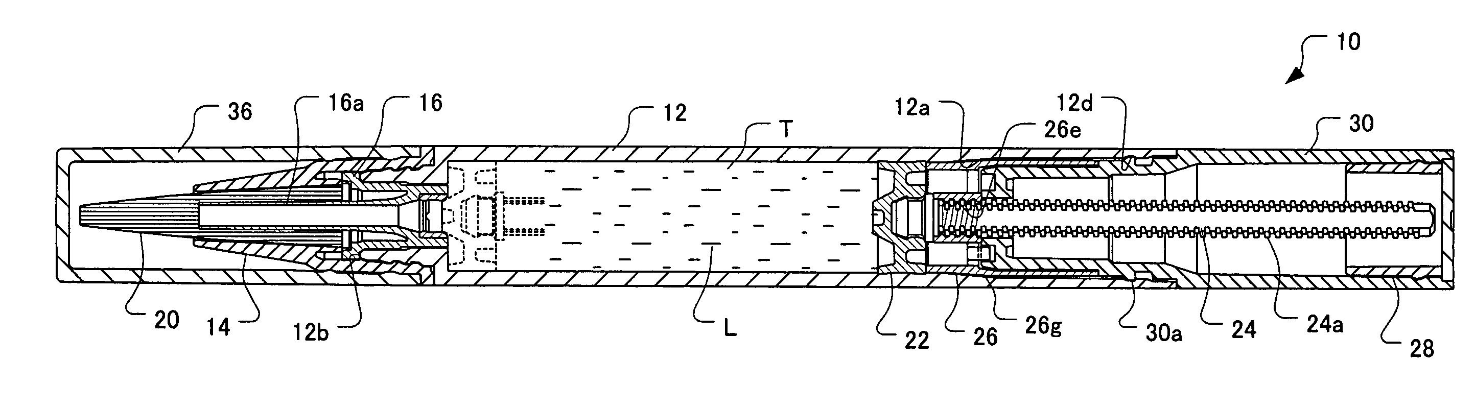
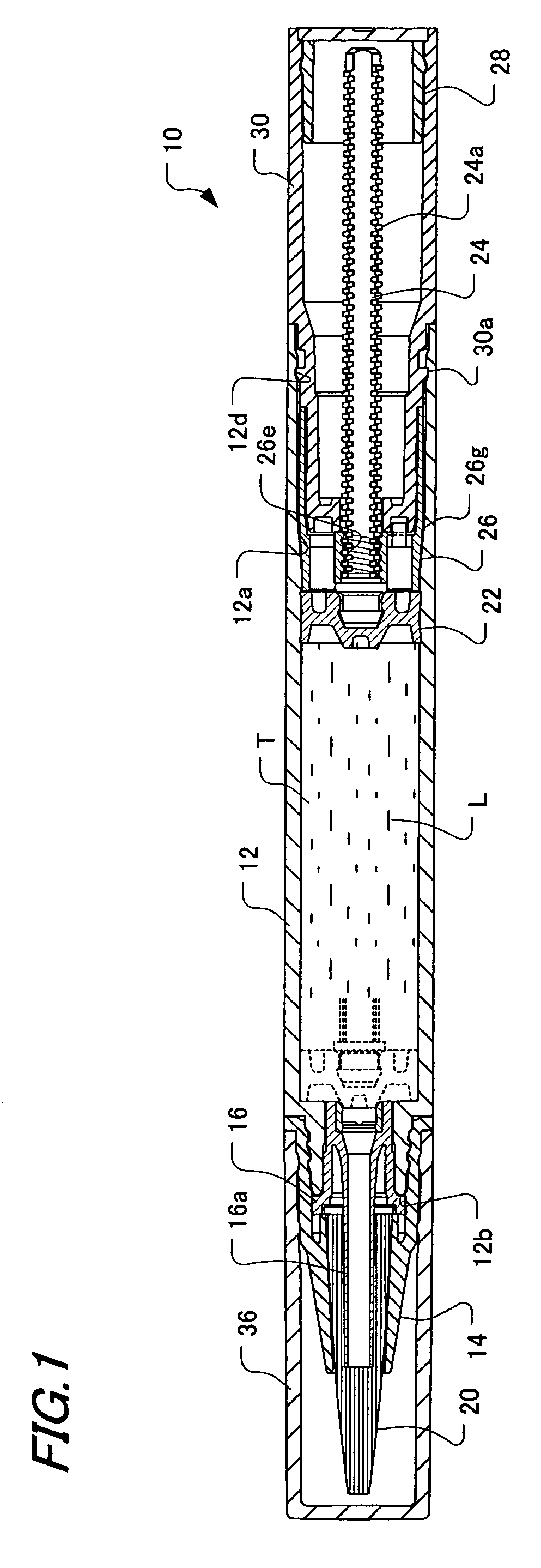
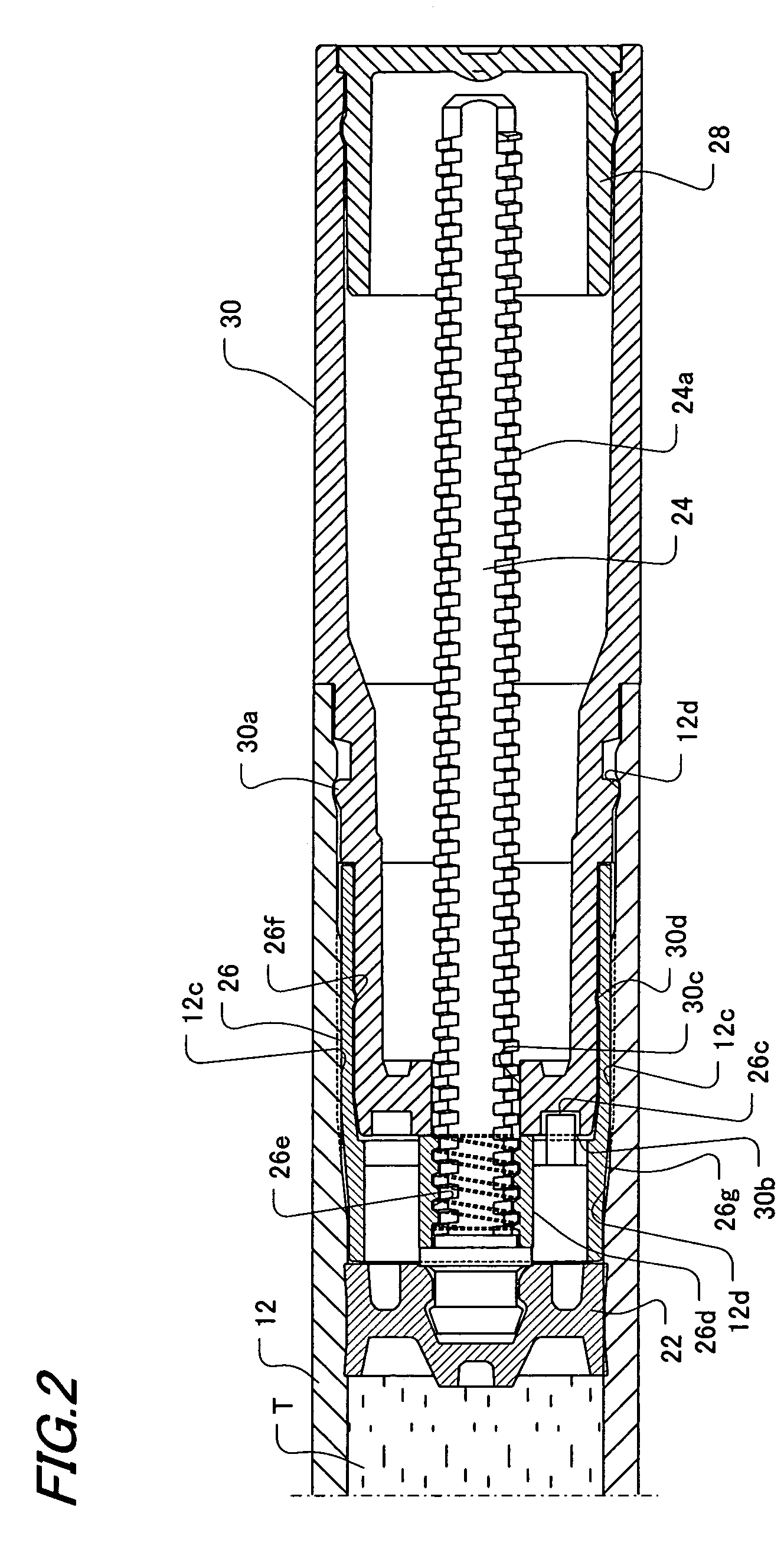
[0024]Hereinafter, an embodiment of the present invention will be explained referring to the drawings. FIG. 1 is an overall longitudinal cross-sectional view showing an embodiment of a liquid container of the present invention, and FIG. 2 is a main cross-sectional view of the liquid container.

[0025]In the drawings, a liquid container 10 includes a body 12 having a tank portion T housing a liquid L such as a correction liquid, writing ink and a cosmetic ink, etc, and having a liquid supply port 12b at a tip end, a leading tool 14 threadably mounted to a tip end of the body 12, a holder 16 which is fixed to the leading tool 14 and has a pipe portion 16a, a brush (tip end coating body) 20, a base portion of which a tip end of a pipe portion 16a is inserted in and is fixed inside the leading tool 14, a piston 22, which is slidable inside the tank portion T, a piston rod 24 which is connected with the piston 22, and extends rearward from the piston, with a male thread 24a being formed on...


PUM


Abstract

The liquid container includes a body for having a tank portion housing a liquid, and having a supply port on a tip end side, a piston for moving forward inside the tank portion, a piston rod connected with the piston and extending rearward, a manipulating cylinder rotatably mounted to a rear portion of the body, and a rotation stopping cylinder unrotatably disposed in a rear inner portion of the body. A conversion mechanism for converting relative rotation between the manipulating cylinder and the body into movement of the piston rod in an axial direction with respect to the body is provided between the manipulating cylinder and the rotation stopping cylinder, and a rotating direction restricting mechanism for restricting the rotating direction of the manipulating cylinder and the body to one direction is provided. The manipulating cylinder and the rotation stopping cylinder are integrally connected by fitting the annular raised portion formed on the rotation stopping cylinder into the annular recessed portion formed on the manipulating cylinder.

Description

BACKGROUND OF THE INVENTION[0001]1. Field of the Invention[0002]The present invention relates to a liquid container for housing a liquid such as cosmetic ink, writing ink and a correction liquid, etc, and supplying the liquid from a tip end side.[0003]2. Description of the Related Art[0004]Conventionally, as a container for housing a liquid of this kind, there is the one described in, for example, Japanese Utility Model Publication No. 6-14844. The liquid container described in this Official Gazette is comprised of a barrel body in which a coating liquid storing portion is formed, a threaded bar projectingly provided at a piston slidably fitted in the storing portion, and a rotary cylinder integrally connecting an inner cylinder member and an outer cylinder member. The outer cylinder member has a ring protruded rib and an engaging claw, which is capable of being resilient in a tip end portion of the outer cylinder member in an axial direction, so that the ring protruded rib is press...

Claims


Application Information

Patent Timeline
Patent Type & Authority Patents(United States)
IPC IPC(8): A45D34/04B65D83/00A45D34/00B43L19/00B43K5/06B43K8/00B43K8/02B43M11/06B65D47/34B65D47/42
CPCA45D34/04B43M11/06B43L19/0018B43K8/00A45D2200/055A45D2034/002
Inventor KAGEYAMA, HIDEHEI
Owner KOTOBUKI PRINTING
Why Eureka
Try Eureka