Subsea protective cap

a protective cap and subsea technology, applied in the field of subsea environment, can solve the problems of subsea wells costing several millions of dollars to drill, affecting the integrity of seals, and exposing the seal pocket on the wellhead, etc., and achieve the effect of improving the protective cap for subsea structures

Inactive Publication Date: 2006-05-30
ARNING MICHAEL DEAN
View PDF48 Cites 22 Cited by
  • Summary
  • Abstract
  • Description
  • Claims
  • Application Information

AI Technical Summary

Benefits of technology

[0026]This invention satisfies the need in the industry for an improved protective cap for subsea structures. A cap for covering an open upper end of a subsea structure is provided which include a base and a body. The base has a size, after shrinkage, at least slightly larger than the exterior of the open upper end of the subsea structure. The body is connected to the base and projects downward from the base. The body has an open bottom. The cap is positioned over the open upper end of the subsea structure with the base of the cap resting on the open upper end of the subsea structure to protect the subsea structure from falling or foreign objects and the body of the cap forming a wall around the exterior of the open upper end of the subsea structure for inhibiting the cap from slipping off the open upper end of the subsea structure.
[0028]Another aspect of the invention provides a plate covered by a corrosive resistant material to form the base and an insert covered by a corrosive resistant material to form the body, wherein the plate and the insert minimize shrinkage of the cap.

Problems solved by technology

The seal pocket on the wellhead is now exposed and vulnerable to dropping and / or foreign objects.
A subsea well can cost several millions of dollars to drill.
Leaving the wellhead exposed to damage from falling objects or other intruders could result in loss of the seal integrity and thereby render the wellhead useless.
Although the '931 patent meets one of the basic requirements (#1: protects the open subsea structure from falling matter and foreign objects), it fails to meet or even disclose any of the other requirements (#2–11) listed above.
This means that it will not work on any other type of subsea structure that does not have the identical mating elements (fails #2).
Additionally, the cap of the '931 patent is designed to work with a drill string tool only (fails #3) and requires orientation (fails #7) and pressure from the tool to latch to and unlatch from the structure (fails #8).
Because the '931 cap requires a complex latching and release mechanism to install and remove the cap, it will not be inexpensive to manufacture or maintain (fails #12).
This design constraint means that there must be different coverings for different applications and the mating / latching requirements mean that the covering is much more expensive to manufacture and maintain.
In general, the approach of the prior art has been to focus on a particular aspect of protection that is very structure-dependent, costly to manufacture and complex to operate.
None of the prior art meets the requirements set forth above.

Method used


Image

  • Subsea protective cap
  • Subsea protective cap
  • Subsea protective cap

Examples


Embodiment Construction

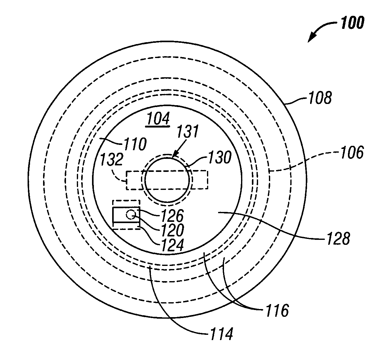
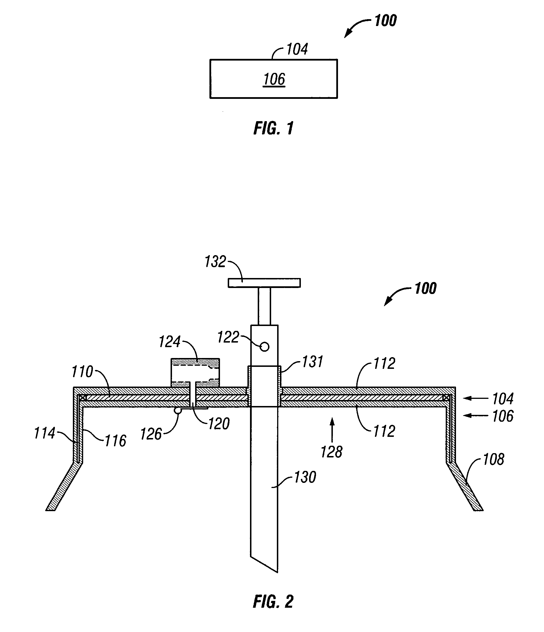
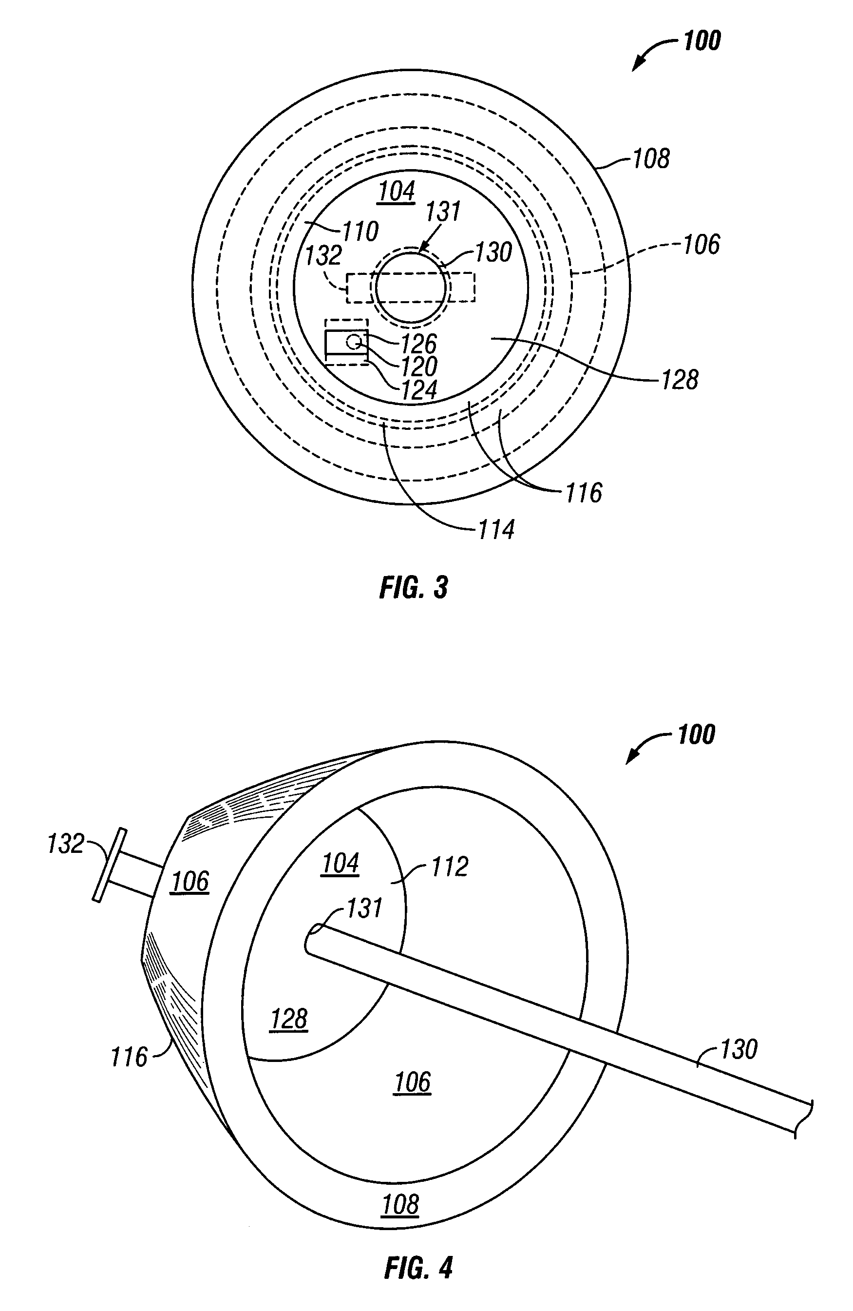
[0037]FIG. 1 is a side view of a cap 100 of the present invention showing the two elements, a base 104 and a body 106, of the cap 100. The body 106 of the cap 100 is open at the bottom and attached to the base 104 at the top of the body 106. The base 104 can be of any shape (such as round, oval, square, rectangular, irregularly-shaped, etc.) that covers the open upper end of the subsea structure. The base 104 of the preferred embodiment, as shown in FIGS. 1 and 2, is circular. This is meant by way of example and is not meant to limit the scope of the invention.

[0038]FIG. 2 is a sectional side view of another embodiment of the present invention also showing the two elements, the base 104 and the body 106, of the cap 100. An inverted funnel or flanged skirt 108 can be added to expedite the installation of the cap 100 onto the structure to be protected. The base 104 of the cap 100 in this embodiment is a circular plate-like structure, which forms the bottom of an inverted bowl shape wh...


PUM


Abstract

A cap for covering an open upper end of a subsea structure includes a base and a body. The base has a size, after shrinkage, at least slightly larger than the exterior of the open upper end of the subsea structure. The body is connected to the base and projects downward from the base. The body has an open bottom. The cap is positioned over the open upper end of the subsea structure with the base of the cap resting on the open upper end of the subsea structure and the body of the cap forms a wall around the exterior of the open upper end of the subsea structure for inhibiting the cap from slipping off the open upper end of the subsea structure.

Description

REFERENCE TO RELATED PROVISIONAL APPLICATION[0001]This application claims the benefit of the filing date of U.S. provisional patent application Ser. No. 60 / 431,962 filed Dec. 9, 2002 by Michael Arning and entitled SUBSEA PROTECTIVE CAP.BACKGROUND[0002]1. Field of the Invention[0003]This invention relates to the subsea environment and specifically to the protection of associated subsea structures such as wellheads, caissons, mud line wells, trees and flowline hubs.[0004]2. Background of the Invention[0005]A typical subsea scenario requiring the installation of a cap commences when an operation, such as drilling a subsea well, is suspended or terminated. During the preceding drilling operation a foundation casing is washed down and inserted into the seabed such that approximately ten feet of the casing protrudes upward from the seabed. A hole is then drilled through the primary foundation and down to a predetermined depth. The next section of pipe is then run into the drilled hole and...

Claims


Application Information

Patent Timeline
Patent Type & Authority Patents(United States)
IPC IPC(8): E21B29/12E21B19/00
CPCE21B33/037
Inventor ARNING, MICHAEL DEAN
Owner ARNING MICHAEL DEAN
Why Eureka
Try Eureka