Capillary for wire bonding and method of wire bonding using it

Active Publication Date: 2006-05-30
ROHM CO LTD
View PDF14 Cites 71 Cited by
  • Summary
  • Abstract
  • Description
  • Claims
  • Application Information

AI Technical Summary

Benefits of technology

[0009]An object of tie present invention is to pro-vide a capillary that permits firm bonding of wire to electrodes in stitch bonding while preventing breakage and peeling-off of the wire after bonding.
[0010]Another object of the present invention is, in a method of wire bonding whereby first bonding is performed on an external electrode and second bonding is performed on a top-surface electrode of a semiconductor device, to prevent breakage and peeling-off of the portion of wire that has been subjected to second bonding.
[0011]To achieve the above objects, according to one aspect of the present invention, a capillary used to perform wire bonding has a face surface formed at the tip end thereof in such a way that the face surface inclines toward the center thereof so as to have a tapered shape, and has a through hole formed therethrough so as to permit wire to be placed therethrough in such a way that the through hole has an opening at the center of the face surface. Here, the angle of inclination of the face surface relative to the plane perpendicular to the axis of the capillary and including the opening of the through

Problems solved by technology

However, with the curved-surface portion 15 of the capillary, t

Method used


Image

  • Capillary for wire bonding and method of wire bonding using it
  • Capillary for wire bonding and method of wire bonding using it
  • Capillary for wire bonding and method of wire bonding using it

Examples


Embodiment Construction

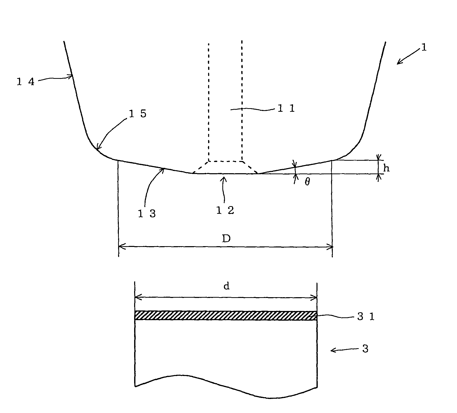
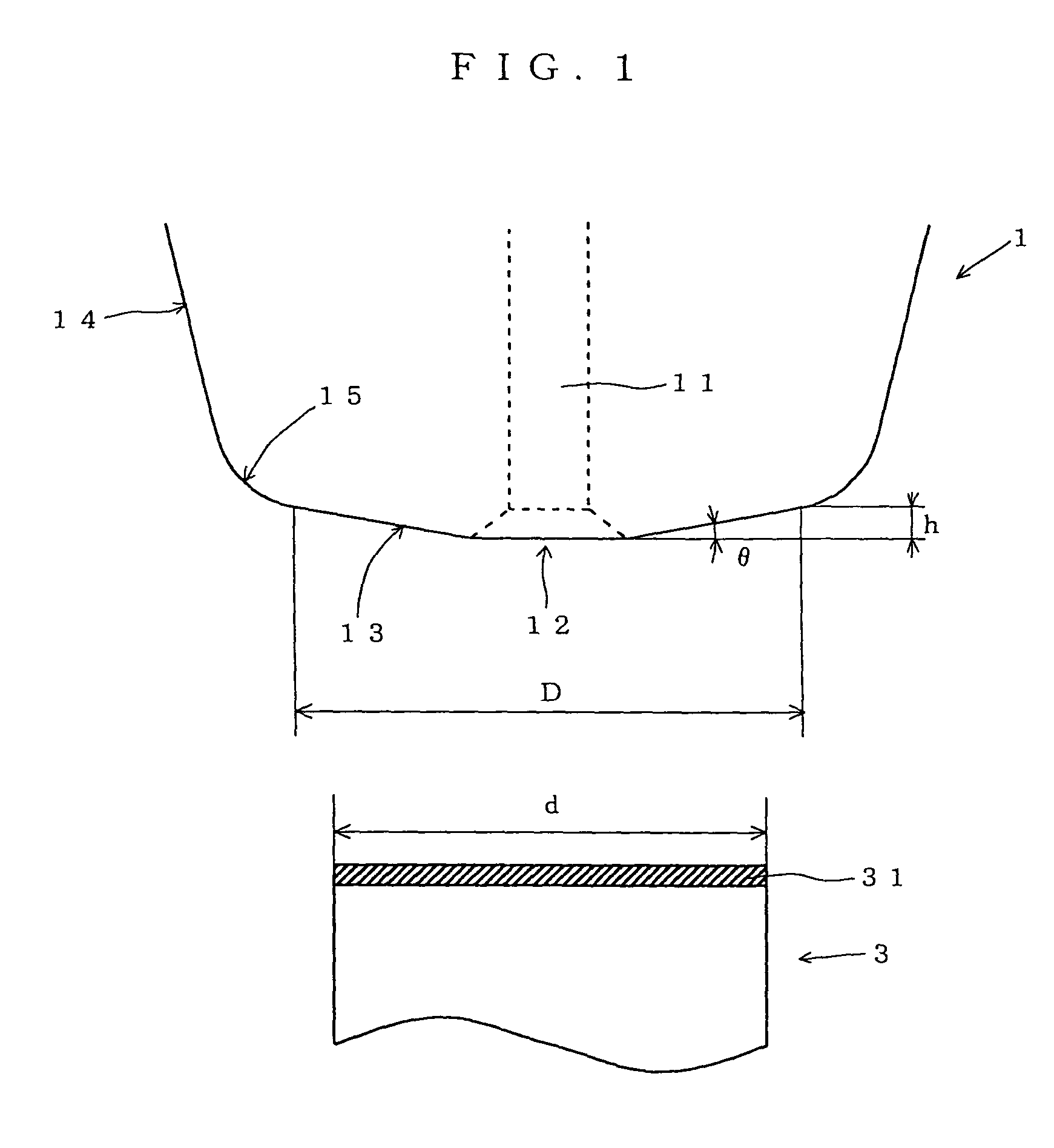
[0018]In search of a way of firmly bonding wire to an electrode in stitch bonding, the inventor of the present invention studied various shapes of the face surface of a capillary, and found that the aim is achieved by giving the face surface an inclination angle and a height in predetermined ranges respectively.

[0019]Specifically, in a capillary according to the present invention, it is important to give its face surface an inclination angle in the range from 4° to 15°. If the inclination angle of the face surface is smaller than 4°, the capillary is too thick relative to the height of the face surface, which will be described later. This makes it difficult to bond wire with high density. On the other hand, if the inclination angle of the face surface is larger than 15°, the pressing force is not sufficiently transmitted to wire via the face surface, resulting in imperfect bonding of the wire to electrodes. A further preferred range of the inclination angle of the face surface is fr...


PUM

PropertyMeasurementUnit
Angleaaaaaaaaaa
Angleaaaaaaaaaa
Angleaaaaaaaaaa

Abstract

A capillary has a face surface 13 formed at the tip end thereof so that the face surface 13 inclines toward the center thereof so as to have a tapered shape, and has a through hole 11 formed therethrough so as to permit wire to be placed therethrough so that the through hole 11 has an opening 12 at the center of the face surface 13. The inclination angle θ of the face surface 13 relative to the plane perpendicular to the axis of the capillary and including the opening 12 of the through hole 11 is in the range from 4° to 15°, and the height h of the face surface 13 along the axis of the capillary is equal to or greater than the thickness of the wire 2.

Description

BACKGROUND OF THE INVENTION[0001]1. Field of the Invention[0002]The present invention relates to a capillary used for wire bonding and to a method of wire bonding using such a capillary. More particularly, the present invention relates to a capillary used to mount semiconductor devices and the like, and to a method of wire bonding using such a capillary.[0003]2. Description of the Prior Art[0004]A conventionally widely practiced method of mounting a semiconductor device on a leadframe or circuit board is wire bonding, a method whereby electrodes are connected together with wires. Common wire bonding is performed roughly in the following manner. First, the tip of wire extracted from a capillary through the opening formed at the tip thereof is formed into a ball-like shape by electric discharge or the like. Then, the capillary is moved to above one electrode and then down so that the tip of the wire formed into the ball-like shape bonds to the electrode (this operation is called first...

Claims


Application Information

Patent Timeline
IPC IPC(8): B23K37/00B23K31/02H01L21/60B23K20/00
CPCB23K20/004H01L24/78H01L24/85H01L24/45H01L2924/01033H01L2224/85186H01L2224/78301H01L2924/01082H01L2924/01079H01L2224/45144H01L2224/48095H01L2224/48471H01L2224/78302H01L2924/01004H01L2924/01005H01L2924/01006H01L2924/00014H01L2924/00H01L24/48H01L2224/45015H01L2224/85205H01L2924/351
Inventor MUTAGUCHI, YOSHIHIKO
Owner ROHM CO LTD
Why Eureka
Try Eureka