Motion detectors and occupancy sensors with improved sensitivity, angular resolution and range

a motion detector and occupancy sensor technology, applied in the field of passive infrared motion detectors and occupancy sensors, can solve the problems of inability to detect horizontal radial motion (e.g. motion directly towards or away from the detector), and achieve the effect of improving increasing the sensitivity and range of motion detectors, and not decreasing the angular resolution of the system

Inactive Publication Date: 2006-05-30
ELECTRO OPTICS TECH
View PDF67 Cites 26 Cited by
  • Summary
  • Abstract
  • Description
  • Claims
  • Application Information

AI Technical Summary

Benefits of technology

[0008]The present invention is a new input lens configuration which can be employed, for example, to: 1) increase the sensitivity and range of motion detectors and occupancy sensors with an entrance aperture of fixed size without decreasing the angular resolution of the system or, 2) improve the angular resolution of a system with an entrance aperture of fixed size without decreasing the sensitivity or range of the system or, 3) decreasing the size of the entrance aperture required for a given sensitivity, range and angular resolution, or 4) reduce the distance that the unit must protrude in, for example, a wallbox installation in order to achieve acceptable performance at wide angles. In one implementation the angular resolution of the system is reduced to zero, i.e. moving infrared radiators anywhere in the field of view of the system are detected, not just radiators that cross the planes separating a sequence of angular sectors. The relative importance of each of these characteristics of motion detectors and occupancy sensors depends on the application in which the system is employed.
[0010]In simplest terms, the infrared input section disclosed herein consists of a lens array, which may be similar to the Fresnel lens array used in the prior art, preceded by one or more, possibly segmented, pre-focusing lenses, which may or may not be Fresnel lenses. For the purpose of illustration, suppose that a certain range and angular resolution can be achieved by employing some particular lens array. If the number of elements of this array is doubled, for example, the angular resolution is improved by approximately a factor of two. However, without changing the size of each element, so as not to affect the sensitivity or range of the system, the size of the array is doubled. This doubling in size can be avoided by employing a pre-focusing lens in front of the customary lens array to focus the beam from any particular incident direction to say, one-half or less of the size of an original lens element. With this configuration the number of elements in the lens array can be effectively doubled, with a corresponding improvement of the angular resolution by a factor of two, without increasing the total size of the lens array or decreasing the sensitivity or range of the system.
[0012]With a high degree of pre-focusing, the size of the individual lens elements making up the final lens array preceding the detector may become too small to be realized by current Fresnel lens technology. In this situation microlens and diffractive optics technology can be employed to produce elements with the same functionality as an array of Fresnel lenses. These elements can be fabricated of low loss plastic by injection molding with single elements as small as a few infrared wavelengths. The use of current microlens and / or diffractive optics techniques to design and fabricate some, possibly all, of the lens elements will produce more capable systems than those that can be produced with current Fresnel lens technology.
[0017]In one particularly interesting implementation, the use of a pre-focusing lens leads to qualitative different performance of a motion detector / occupancy sensor than in the prior art. In this implementation the width of the pre-focused beam on the front surface of the lens array is made equal to the width of one element of the lens array. In order to understand the performance of this system, suppose that the infrared source is in a position such that the pre-focused beam just fills one element of the lens array. As the infrared source moves in either direction, the total power illuminating that element of the lens array is reduced and continues to decrease until the beam moves completely off of one side or the other of the element of the lens array. The system can be designed so that, for the entire small range of angles for which the element of the lens array is partially illuminated, this radiation is focused onto the active area of a detector. As the source moves over this small range of angles, the infrared power incident on the detector varies, which produces a corresponding electrical output that is processed to determine the state of motion of the infrared source. This configuration produces a detectable signal at useful source ranges because: 1) of the greater collecting power of the pre-focusing lens, as opposed to the collecting power of a single element of the Fresnel lens array as in the prior art; and 2) the size of each element of the lens array can be greatly reduced, since it is not employed as a collecting element.
[0019]It is not unusual for prior art occupancy sensors and motion detectors to employ a small number of Fresnel lens arrays side by side on the front surface of the unit. These arrays are designed to have different fields of view and / or different ranges. According to the present invention the size of one particular lens element in the array may be made small enough such that many rows of lenses can be employed in a practical system. With such a truly two-dimensional array of lenses, qualitatively different performance can be achieved than in the prior art. Specifically, prior art systems can only detect motion in one angular direction. With a two-dimensional array of lenses motion can be detected in three-directions. For example, with a wallbox or wall mounted system a vertically mounted two-dimensional array can clearly detect vertical as well as angular horizontal motion. Such a system can also detect radial motion in the horizontal plane because an infrared source moving in this direction is also changing its angle with respect to a vertical through the lens array. A properly designed pre-focusing lens and two-dimensional array can also give information about the angular size and range of a moving infrared source. This would greatly increase the noise rejection capabilities of the system.

Problems solved by technology

Further, such systems can detect horizontal radial motion (e.g. motion directly towards or away from the detector) which is not possible with prior art systems which can only detect infrared radiators moving across the planes which separate a sequence of angular sectors.

Method used


Image

  • Motion detectors and occupancy sensors with improved sensitivity, angular resolution and range
  • Motion detectors and occupancy sensors with improved sensitivity, angular resolution and range
  • Motion detectors and occupancy sensors with improved sensitivity, angular resolution and range

Examples


Embodiment Construction

[0039]Turning now to the drawings, in which like reference numerals identify similar or identical elements throughout the several views,

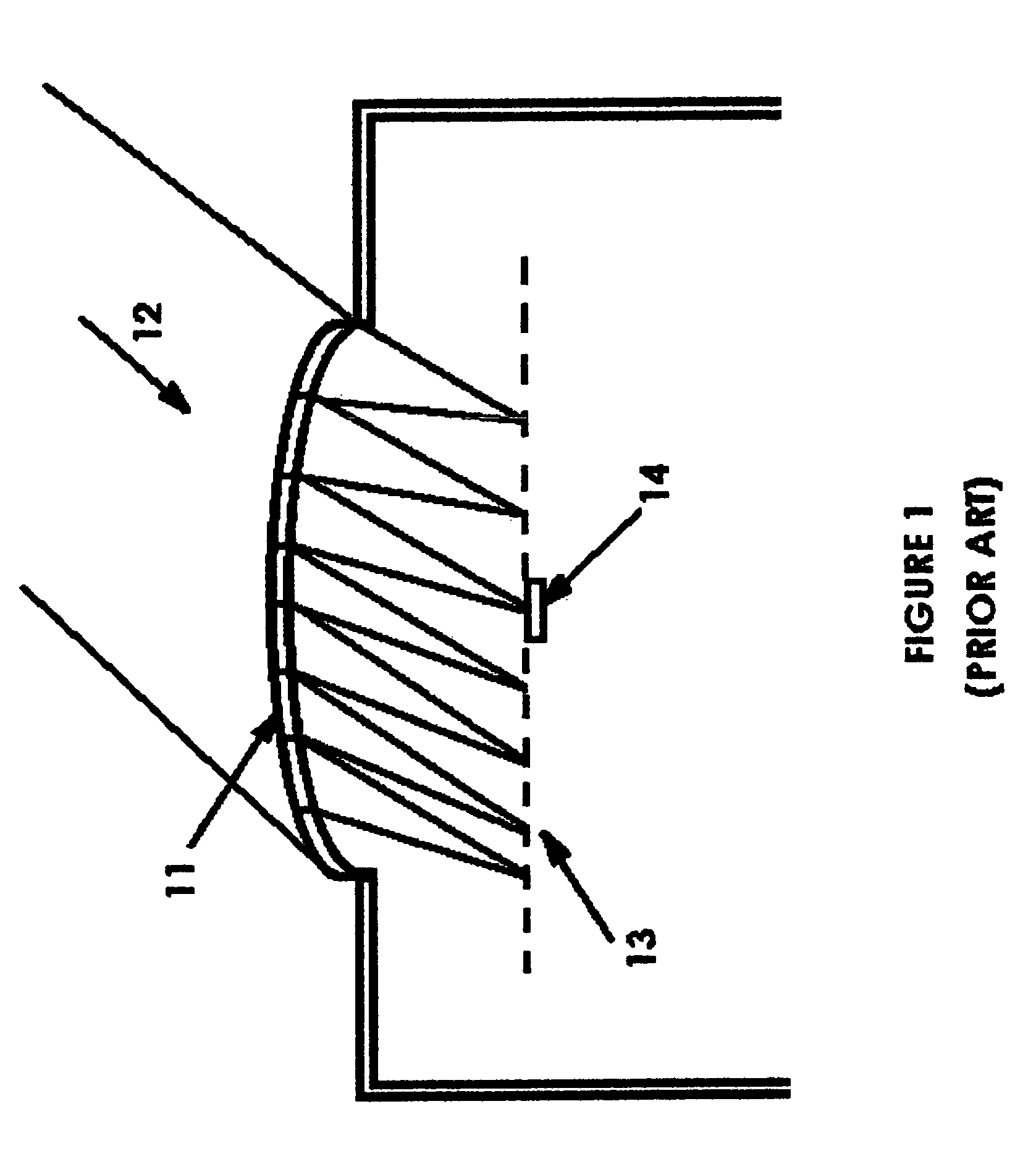
[0040]FIG. 1 shows the input section of a typical passive infrared motion detector / occupancy according to prior art. A Fresnel lens array 11 spans the entrance aperture. Each element of the Fresnel lens array 11 intercepts a small fraction of the input infrared radiation 12 incident from some particular direction and focuses it to a spot 13 in the focal plane of that element. This leads to a number of focal spots equal to the number of elements of the Fresnel lens array 11. For simplicity we have shown all of the focal spots in one plane. If the source of the infrared radiation is moving, the angle of incidence of the incident radiation changes and the system of focal spots moves across the active area of a detector 14. Thus, as the source moves, the electrical output of the detector changes abruptly as a spot moves onto or off of the active area of...


PUM


Abstract

Methods and apparatus are disclosed for improving the sensitivity, angular resolution and range of motion detectors, occupancy sensors and similar systems. Specifically, an improved infrared input section is described which employs at least one additional lens, possibly segmented, before a lens array. This pre-focusing lens collects incident infrared radiation over the entire entrance aperture and partially focuses it onto one element of the lens array. The final lens array which focuses the radiation onto a detector may be an array of Fresnel lenses as in the prior art, an array of microlenses or a diffractive optics array. It is also possible to implement this system is such a way that moving infrared sources at any angular orientation will be detected as opposed to prior art systems in which only sources which cross the planes separating an array of angular sectors are detected.

Description

CROSS REFERENCE TO RELATED APPLICATIONS[0001]This application claims priority from and is a division of U.S. application Ser. No. 09 / 830,594 filed on Jul. 18, 2001, now U.S. Pat. No. 6,690,018, which is a 371 of International Application No. PCT / US99 / 25161 filed on Oct. 27, 1999, which claims benefit of U.S. Provisional Application Nos. 60 / 106,323 filed Oct. 30, 1998 and 60 / 143,209 filed Jul. 9, 1999.BACKGROUND OF THE INVENTION[0002]1. Field of the Invention[0003]The present invention relates to passive infrared motion detectors, occupancy sensors and similar devices, and more particularly to the infrared input section of these devices.[0004]2. Description of the Related Art[0005]Passive infrared motion detectors and occupancy sensors employ an array of Fresnel lenses covering an entrance aperture. This lens array is illuminated by thermal infrared radiation from the object of interest. For any particular angle of incidence each of the elements in the array of Fresnel lenses coverin...

Claims


Application Information

Patent Timeline
Patent Type & Authority Patents(United States)
IPC IPC(8): G08B13/193
CPCG08B13/193Y10S250/01
Inventor BARONE, STEPHEN
Owner ELECTRO OPTICS TECH
Why Eureka
Try Eureka