
Bias-adjusted giant magnetoresistive (GMR) devices for magnetic random access memory (MRAM) applications

a giant magnetoresistive and random access memory technology, applied in the field of magnetic random access memory applications, can solve the problems of asymmetric hysteresis curve, high word current requirements for reliable operation, and often biased hysteresis curve of gmr devices

Inactive Publication Date: 2006-05-30
HONEYWELL INT INC
View PDF22 Cites 9 Cited by
  • Summary
  • Abstract
  • Description
  • Claims
  • Application Information

AI Technical Summary

Benefits of technology

The present invention provides a magnetoresistive device that can change its resistance when a magnetic field is applied. The device includes a reference layer, a switching layer, and a nonmagnetic conductor layer between the reference layer and the switching layer. The reference layer has a fixed magnetization direction when the magnetic field is applied, while the switching layer has a changing magnetization direction. The device also includes a first ferromagnetic layer, a second ferromagnetic layer, and a second nonmagnetic conductor layer between the first and second ferromagnetic layers. The magnetic coupling between the first and second ferromagnetic layers is predominantly magnetostatic. The invention also provides a magnetoresistive device with a variable resistance that varies with applied magnetic field over a range of applied magnetic fields. The device has a hysteresis curve that is substantially symmetric about zero applied magnetic field.

Problems solved by technology

One difficulty with conventional GMR devices for MRAM applications, e.g., for write and / or read operations, depending on the architecture, is that the hysteresis curve for a GMR device is often substantially “biased,” i.e., asymmetric with respect to applied magnetic field. FIG. 3 illustrates such a biased or asymmetric hysteresis curve.
Several disadvantages may result from this asymmetric hysteresis curve.
Second, the asymmetry of the hysteresis curve may cause higher word currents to be required for reliable operation.
In particular, since word currents of the same magnitude but different directions are typically used to write data to the GMR devices in an MRAM memory element, a word current that generates an applied magnetic field with magnitude H0 may be insufficient.
However, when flowing in the other direction, the word current may be unable to place the GMR device in the “1” state with resistance R1.

Method used


Image

  • Bias-adjusted giant magnetoresistive (GMR) devices for magnetic random access memory (MRAM) applications
  • Bias-adjusted giant magnetoresistive (GMR) devices for magnetic random access memory (MRAM) applications
  • Bias-adjusted giant magnetoresistive (GMR) devices for magnetic random access memory (MRAM) applications

Examples


Embodiment Construction

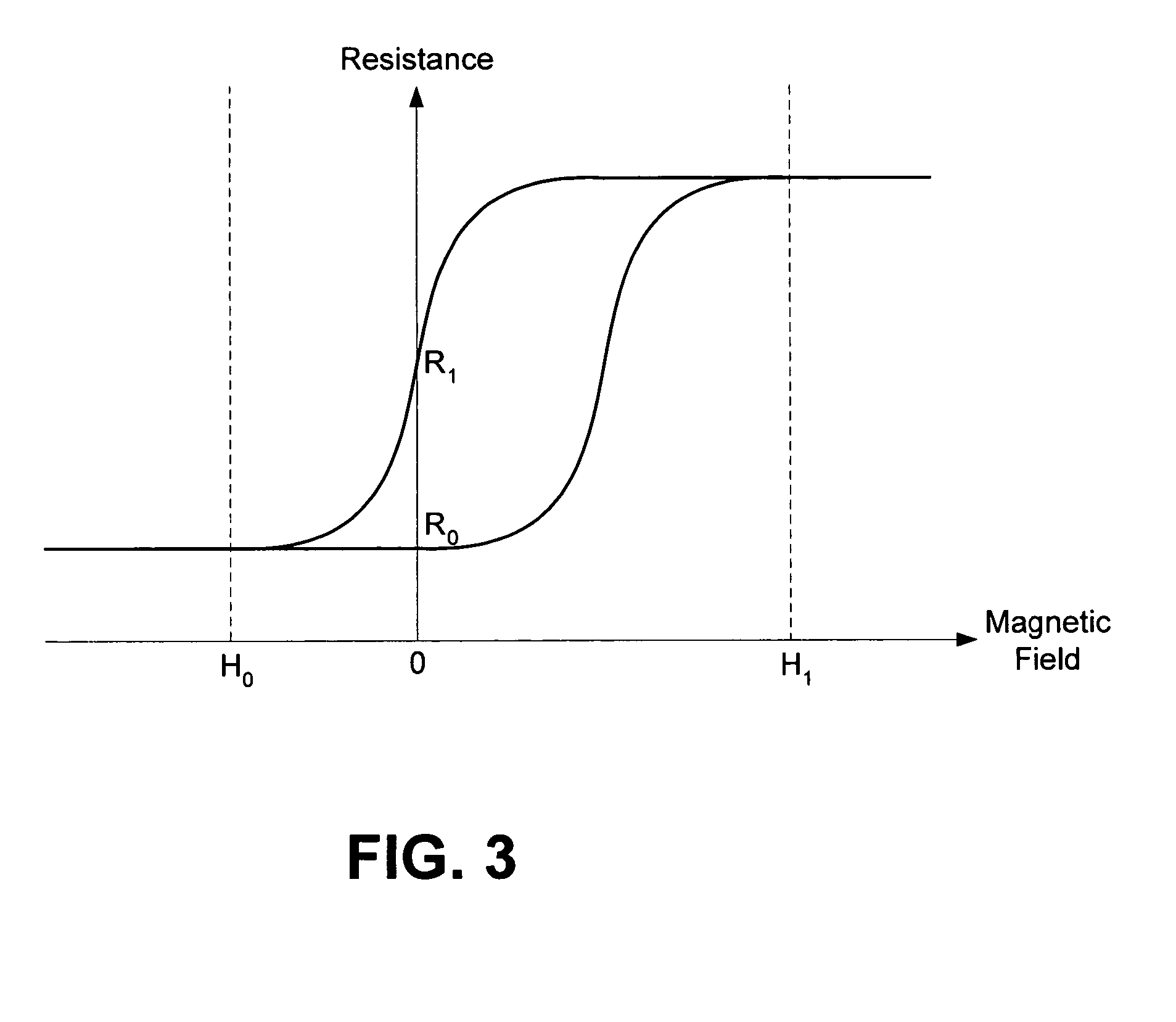
[0023]The present invention, in its preferred embodiments, provides GMR devices, such as spin valves or pseudo spin valves, with hysteresis curves that are substantially symmetric about zero applied magnetic field. FIG. 4 shows an example of such a substantially symmetric hysteresis curve. As shown in FIG. 4, the difference between the highest resistance and lowest resistance is maximal at near zero applied magnetic field. The highest zero-field resistance, R1, may be achieved by applying and then removing magnetic field, H1, and the lowest zero-field resistance, R0, may be achieved by applying and then removing magnetic field H0. Ideally, H1 and H0 represent magnetic fields of the same magnitude but opposite direction, so that they can be generated by the same word current flowing in opposite directions. Although FIG. 4 illustrates a perfectly symmetric hysteresis curve, it is to be understood that GMR devices with hysteresis curves that are substantially, though not perfectly, sym...


PUM

PropertyMeasurementUnit
resistanceaaaaaaaaaa
magnetizationaaaaaaaaaa
magnetic fieldaaaaaaaaaa

Abstract

A bias-adjusted giant magnetoresistive (GMR) device includes a ferromagnetic reference layer, which has a magnetization that remains relatively fixed when a range of magnetic fields is applied, and a ferromagnetic switching layer, which has a magnetization that can be changed by applying a relatively small magnetic field. In MRAM applications, the switching layer stores data in the form of the particular orientation of its magnetization relative to the magnetization of the reference layer. At least one of the reference and switching layers is split into at least two ferromagnetic layers separated by one or more layers of a nonmagnetic conductor, such that the hysteresis curve of resistance versus applied magnetic field is substantially symmetric about zero applied magnetic field.

Description

GOVERNMENT RIGHTS[0001]The United States Government has acquired certain rights in this invention pursuant to Contract No. DTRA01-00-C-0002 awarded by DTRA.BACKGROUND[0002]1. Field[0003]The present invention relates generally to magnetoresistive devices and, more particularly, to giant magnetoresistive devices for magnetic random access memory applications.[0004]2. Related Art[0005]The discovery of the giant magnetoresistive (GMR) effect has led to the development of a number of spin-based electronic devices. The GMR effect is observed in certain thin-film devices that are made up of alternating ferromagnetic and nonmagnetic layers. The resistance of a GMR device is typically lowest when the magnetic moments of the ferromagnetic layers are in a parallel orientation and highest when the magnetic moments are in an antiparallel orientation.[0006]One type of GMR device is commonly referred to as a “spin valve.” A spin valve typically includes two ferromagnetic layers that are separated ...

Claims


Application Information

Patent Timeline
Patent Type & Authority Patents(United States)
IPC IPC(8): H01L31/119G11B5/39G11C11/16H01F10/32H01F41/18H10N50/10
CPCB82Y25/00G11B5/39H01L43/08H01F10/3272H01F10/3281G11C11/16H10N50/10
Inventor KATTI, ROMNEY R.
Owner HONEYWELL INT INC
Learn More