Device and method for monitoring the connection of an electrical supply unit

a technology for monitoring devices and electrical supply units, applied in the direction of dynamo-electric converter control, dynamo-electric gear control, instruments, etc., can solve problems such as faulty connection wiring, and achieve the effect of low effort and expense for computation

Inactive Publication Date: 2006-05-30
ROBERT BOSCH GMBH
View PDF9 Cites 27 Cited by
  • Summary
  • Abstract
  • Description
  • Claims
  • Application Information

AI Technical Summary

Benefits of technology

[0005]In an expedient refinement, it is provided that the monitoring device evaluates the longitudinal current for monitoring the connection. Particularly if all the phase-related powers are negative, the phase shift by either +120° or −120° can be detected unambiguously from the longitudinal current. By including the longitudinal current, all possible faulty connections can now be detected unambiguously. Since on the other hand the longitudinal current is already available in the context of field-oriented regulation, this evaluation assures low effort and expense for computation. Further expedient refinements will become apparent from the further dependent claims and from the description.

Problems solved by technology

In all other cases, conversely, in which the transverse current permanently or briefly assumes a positive value during the activation operation, it can be concluded that there is faulty connection wiring.

Method used


Image

  • Device and method for monitoring the connection of an electrical supply unit
  • Device and method for monitoring the connection of an electrical supply unit
  • Device and method for monitoring the connection of an electrical supply unit

Examples


Embodiment Construction

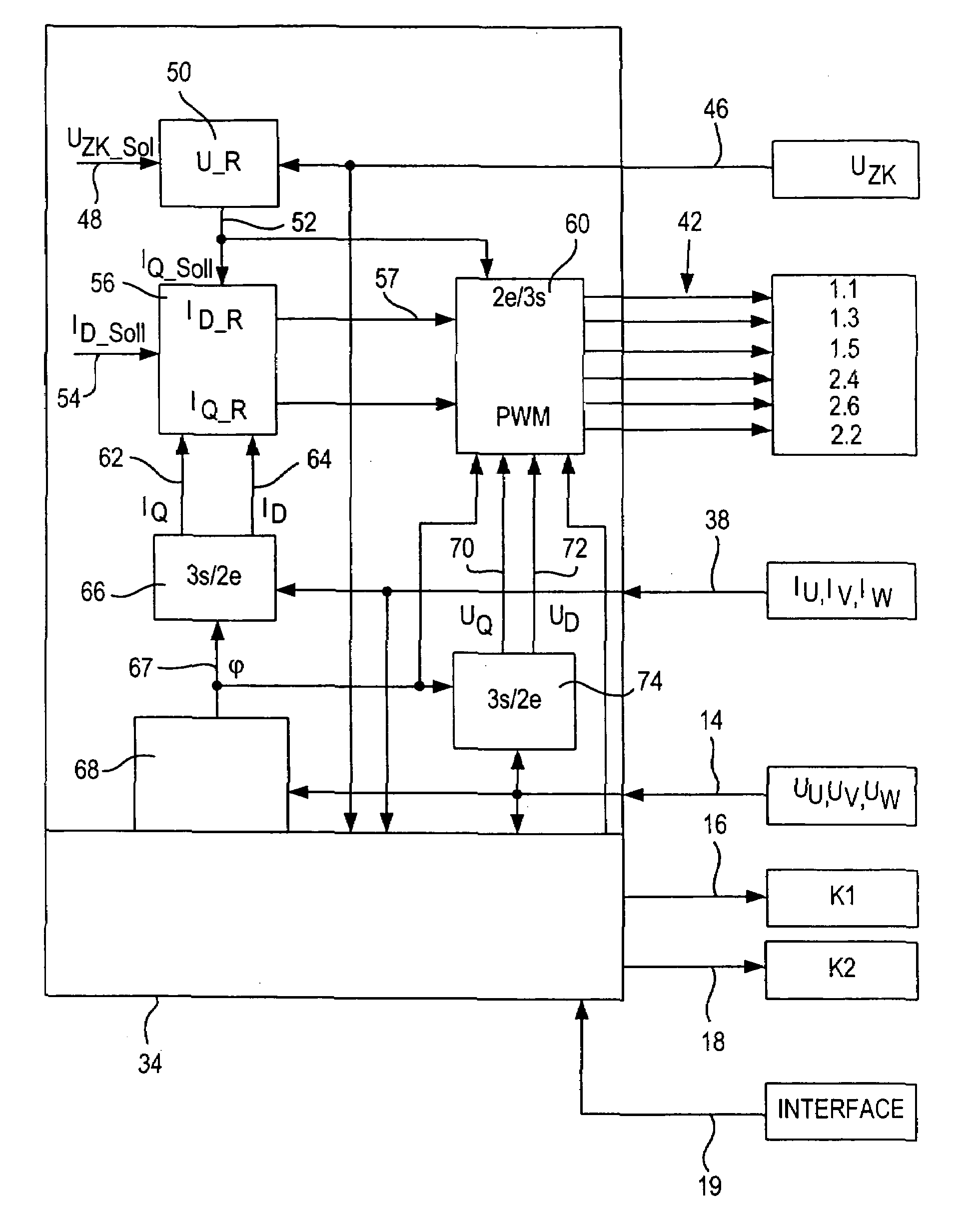
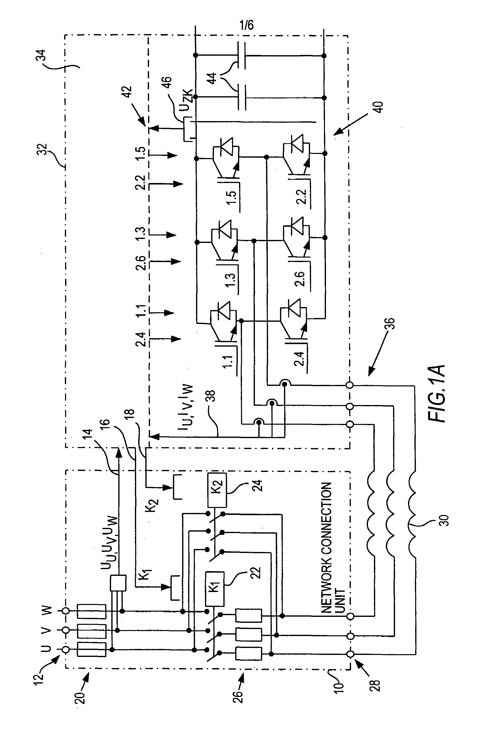
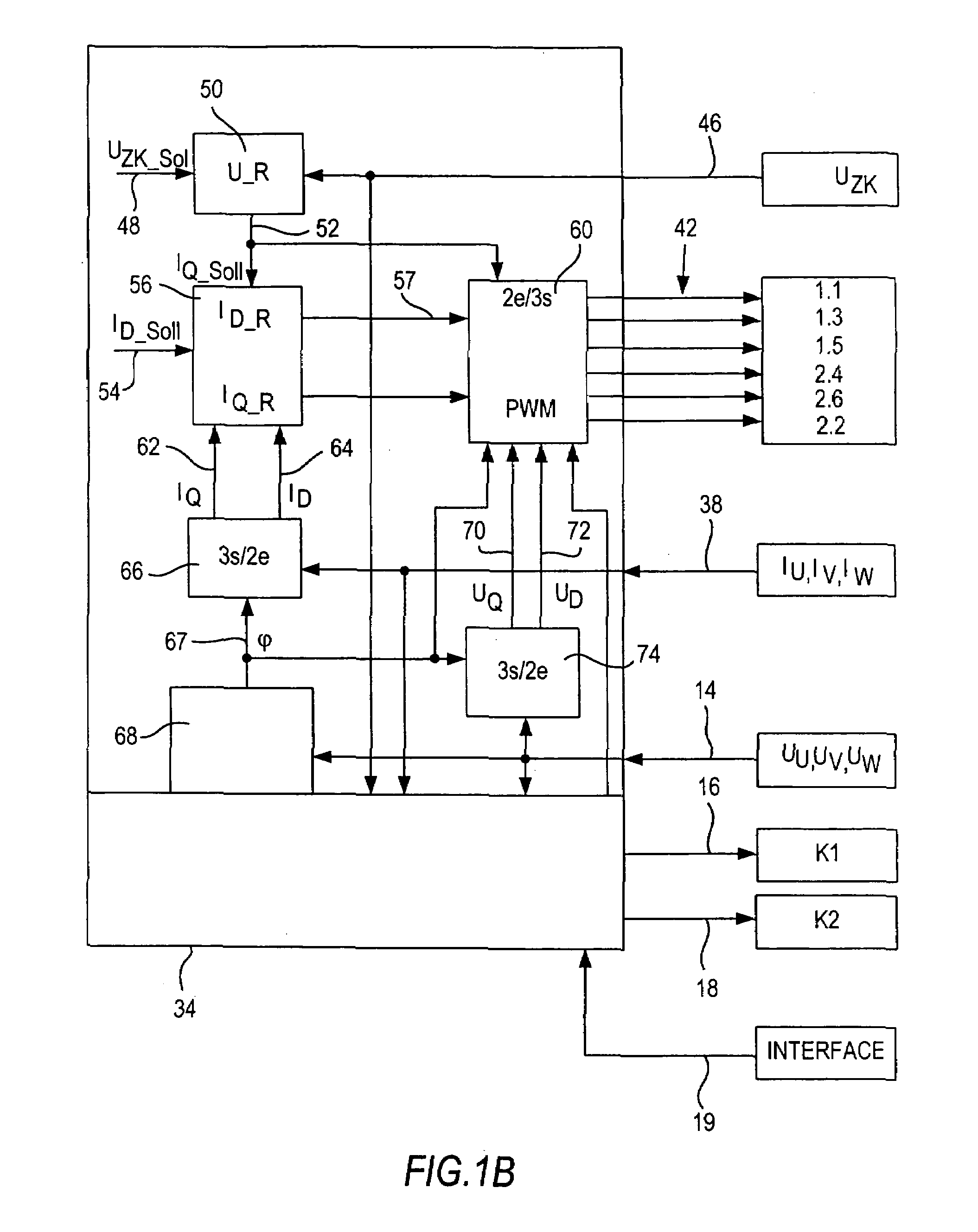
[0011]Via a network connection 12, the three phases U, V, W of a rotary current network (360 to 510 V, 50 / 60 Hz) are supplied to a network connection unit 10. Each of the three phases U, V, W is protected via a fuse 20. Downstream of the fuses 20 in terms of the network, the phase voltages UU, UV, UW 14 are picked up and delivered to a regulation and control block 34 of a supply unit 32. This regulation and control block 34 furnishes a first and second protective trigger signal 16, 18 for triggering a charge contactor 22 and a network contactor 24, which is integrated with the network connection unit 10. If the charge contactor 22 is triggered by a suitable trigger signal 16 in the direction of closure, then the phase currents IU, IV, IW, via charge resistors 26, reach the respective reactor connection points 28 in the form of outputs of the network connection unit 10. The charge resistors 26 are bridged by the network contactor 24, once the charging operation of the intermediate ci...


PUM


Abstract

The invention relates to a device and a method for monitoring the connection of an electrical supply unit comprising voltage detection (32) detecting phase voltage (14), current detection (32) detecting phase voltages (38), a transformation unit (66) transforming the phase voltages (38) after conducting field-oriented regulation in at least one cross current (62), wherein a monitoring device (34) is provided to monitor at least one supply connection (28, 36) by means of which an electrical supply unit (32) is supplied, said monitoring unit evaluating the variation of the cross current (62) in order to monitor the connection.

Description

BACKGROUND OF THE INVENTION[0001]The invention is based on a device and a method for monitoring the connection of an electrical supply unit. From German Patent DE 42 13443 C1, a circuit arrangement for monitoring the failure of fuses is already known. The fuses are each connected into the current paths of a rotary current network for supplying a consumer. The circuit arrangement has a first delta-connection circuit for detecting the phase of a voltage between each two conductors of the rotary current network upstream of the fuses and a second delta circuit for detecting the phase of a voltage between each two conductors of the rotary current network downstream of the fuses. The respective phases upstream and downstream of the fuses are compared with one another, and a failure signal is output if a phase difference occurs, or if one or more phases are absent. This circuit is also suitable for monitoring the connection of an electrical supply unit.[0002]The object of the invention is ...

Claims


Application Information

Patent Timeline
Patent Type & Authority Patents(United States)
IPC IPC(8): G01R31/08G01R25/00G01R31/36G01R31/02H02H7/08H02H11/00H02M7/12H02P21/00H02P21/34
CPCH02P21/0032H02P21/00H02H11/004H02H7/0838H02P21/34
Inventor MONTER, LEOBARINBERG, VIKTOR
Owner ROBERT BOSCH GMBH
Why Eureka
Try Eureka