System and method for monitoring and controlling remote devices

a remote device and system technology, applied in the field of remote system monitoring, reporting on, and controlling remote systems, can solve the problems of inherently inefficient aperiodic monitoring systems (those that do not operate, cycle) and the cost associated with the sensor-actuator infrastructure required to monitor and control functions within such systems

Inactive Publication Date: 2006-05-30
SIPCO
View PDF233 Cites 707 Cited by
  • Summary
  • Abstract
  • Description
  • Claims
  • Application Information

AI Technical Summary

Benefits of technology

[0018]In more robust embodiments, a system can be configured to collect, format, and deliver client application specific information on a periodic basis to predetermined client nodes on the WAN. In these embodiments, client intervention would serve to close the feedback loop in the control system.
[0021]In yet a further embodiment, a system can be configured using the present invention to translate and transmit control signals from an existing local controller via the networked wireless transceivers. In this regard, the system of the present invention would require a data translator to tap into the data stream of an existing control system. Distinct control system signals may be mapped to function codes used by the present invention in order to provide customer access to control system data. In this way, the system of the present invention can be integrated with present data collection and system controllers inexpensively, as customers will only have to add a data translator and a wireless transmitter or transceiver as the application demands. By integrating the present invention with the data stream generated by present monitoring and control systems, potential customers enjoy the benefits of the present invention without the difficulties associated with integrating sensors and actuators to monitor individual system parameters.

Problems solved by technology

Aperiodic monitoring systems (those that do not operate on a predetermined cycle) are inherently inefficient as they require a service technician to physically traverse an area to record data, repair out of order equipment, add inventory to a vending machine, and the like.
A problem with expanding the use of control systems technology to distributed systems are the costs associated with the sensor-actuator infrastructure required to monitor and control functions within such systems.
Not only is there expense associated with developing and installing appropriate sensors and actuators but the added expense of connecting functional sensors and controllers with the local controller.
Another prohibitive cost associated with applying control systems technology to distributed systems is the installation and operational expense associated with the local controller.

Method used


Image

  • System and method for monitoring and controlling remote devices
  • System and method for monitoring and controlling remote devices
  • System and method for monitoring and controlling remote devices

Examples


Embodiment Construction

[0041]Having summarized the invention above, reference is now made in detail to the description of the invention as illustrated in the drawings. While the invention will be described in connection with these drawings, there is no intent to limit it to the embodiment or embodiments disclosed therein. On the contrary, the intent is to cover all alternatives, modifications and equivalents included within the spirit and scope of the invention as defined by the appended claims.

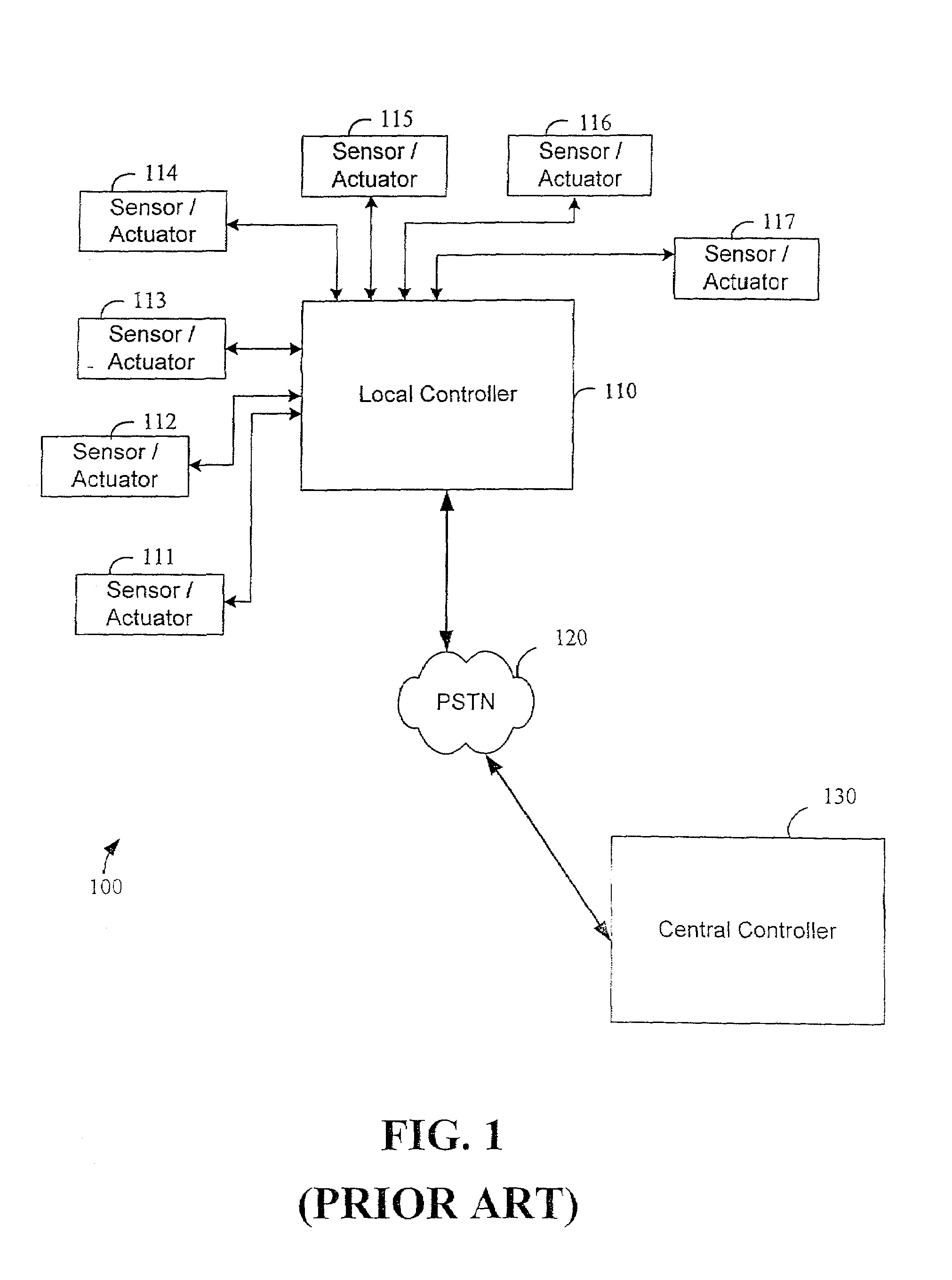
[0042]Referring now to the drawings, reference is made to FIG. 1, which is a block diagram illustrating certain fundamental components of a prior art control system 100. More particularly, a prior art control system 100 includes a plurality of sensor actuators 111, 112, 113, 114, 115, 116, and 117 electrically coupled to a local controller 110. In a manner well known in the art of control systems, local controller 110 provides power, formats and applies data signals from each of the sensors to predetermined process...


PUM


Abstract

The present invention is generally directed to a system for monitoring a variety of environmental and / or other conditions within a defined remotely located region. In accordance with one aspect of the invention, a system is configured to monitor utility meters in a defined area. The system is implemented by using a plurality of wireless transmitters, wherein each wireless transmitter is integrated into a sensor adapted to monitor a particular data input. The system also includes a plurality of transceivers that are dispersed throughout the region at defined locations. The system uses a local gateway to translate and transfer information from the transmitters to a dedicated computer on a network. The dedicated computer, collects, compiles, and stores the data for retrieval upon client demand across the network. The computer further includes means for evaluating the received information and identifying an appropriate control signal, the system further including means for applying the control signal at a designated actuator.

Description

CROSS-REFERENCE TO RELATED APPLICATIONS[0001]This application is a continuation of U.S. patent application Ser. No. 09 / 439,059, filed on Nov. 12, 1999, now U.S. Pat. No. 6,437,692 which was a continuation-in-part of U.S. patent application Ser. No. 09 / 271,517; filed Mar. 18, 1999, now abandoned and entitled, “System For Monitoring Conditions in a Residential Living Community;” Ser. No. 09 / 102,178; filed Jun. 22, 1998, now U.S. Pat. No. 6,430,268 entitled, “Multi-Function General Purpose Transceiver;” Ser. No. 09 / 172,554; filed Oct. 14, 1998, now U.S. Pat. No. 6,028,522 entitled, “System for Monitoring the Light Level Around an ATM;” Ser. No. 09 / 412,895; filed Oct. 5, 1999, now U.S. Pat. No. 6,218,953 entitled, “System and Method for Monitoring the Light Level Around an ATM” and further claims the benefit of provisional patent application Ser. No. 60 / 146,817; filed Aug. 2, 1999 entitled, “System and Method for Monitoring and Controlling Residential Devices.” Each of the above identif...

Claims


Application Information

Patent Timeline
Patent Type & Authority Patents(United States)
IPC IPC(8): G08B1/00G01D4/00G05B19/042G05B19/418G08B21/00G08C17/02H04L29/06H04M11/04H04W4/38
CPCG01D4/004H04W4/006G05B19/4185G08B25/007G08B25/009G08C17/02H04L12/2825H04L29/06H04M11/04H04Q9/00H04L67/12G05B19/042G05B2219/25198G05B2219/31162G07C5/008G08C2201/40G08C2201/42G08C2201/51Y02B90/242Y04S20/322H04L69/08H04Q2209/40H04Q2209/60H04W4/38Y02B90/20Y02P90/02Y04S20/30H04L9/40
Inventor PETITE, THOMAS D.HUFF, RICHARD M.
Owner SIPCO
Why Eureka
Try Eureka