Underground object locator

a locator and underground technology, applied in the field of downhole locators, can solve the problems of inability to choose the communication method between ground and surface, unsatisfactory, and dependent, and achieve the effect of reducing the effectiveness of the sonde communication channel and wasting module energy in heating the battery

Active Publication Date: 2006-05-30
RADIODETECTION
View PDF7 Cites 41 Cited by
  • Summary
  • Abstract
  • Description
  • Claims
  • Application Information

AI Technical Summary

Benefits of technology

[0008]In an embodiment of the invention, the sonde operates by communicating by modulation of the EM emission. Because of the small volume in the sonde it is advantageous for the sonde to function in the same manner whether the sonde is operating in wireline or battery mode, in order to minimise component requirements, which would otherwise be required to make use of one communication method when in wireline operation and a second method of communication when in battery operation. In another embodiment, the sonde has a battery fitted in it at all times.
[0011]Standard sonde radiative emission modulation is at a frequency of many KHz. While such a frequency is suitable when the sonde is battery operated, at such frequencies, a battery cannot be included in the wireline circuit when the sonde is operating as a wireline sonde. This is because, at such frequencies, the battery acts as a capacitor in paralel with the wireline to the surface and the antenna. The battery therefore smooths and absorbs any AC modulation signal from the antenna passing through it by presenting a low impedence path across the circuit, and the modulation energy is wasted in heating the battery, so reducing the effectiveness of the sonde communication channel.

Problems solved by technology

As stated above, because of the requirement for small size of sondes, separate communication methods between ground and surface, depending upon whether the sonde is wireline or battery operated, are not desirable.

Method used


Image

  • Underground object locator
  • Underground object locator
  • Underground object locator

Examples


first embodiment

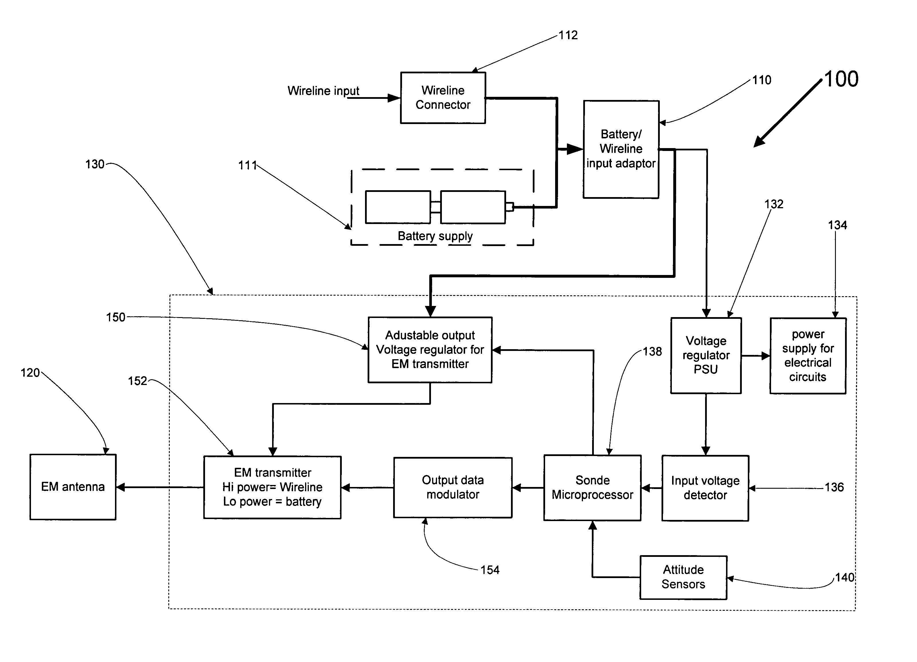
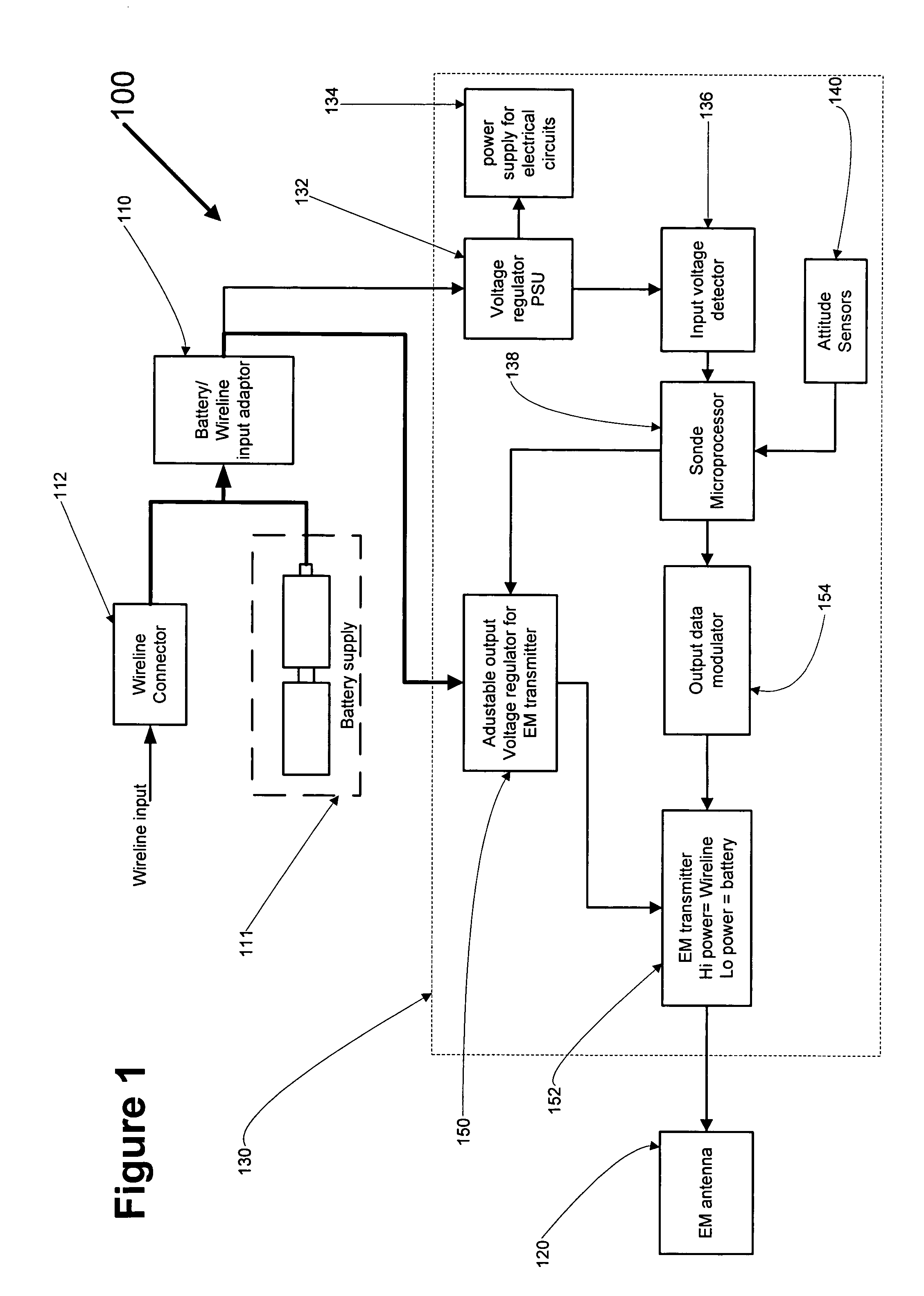
[0035]FIG. 1 shows a data sonde 100 according to a The data sonde 100 comprises a power supply receiving unit 110, which receives either a wireline 120 from a surface control unit, or one or more batteries 125 for alternative power of the data sonde 100 when a wireline 111 is not connected to it through the power supply receiving unit 110.

[0036]An antenna 120 is also provided, which is connected to the power supply receiving unit 110, and which emits an electromagnetic signal. Control circuitry 130 is also provided, which controls the emission of the antenna 120.

[0037]The power supply receiving unit 110 comprises a female recess, into which can be placed either one or more batteries 111, or a male connector 112 from a wireline, depending upon whether the sonde 100 is to be battery powered or wireline powered. The antenna 120 is controlled by the control circuitry 130 and radiates an electromagnetic field for use in determining the location of the sonde 100, which can be detected by...

fourth embodiment

[0059]FIG. 10 shows a surface control unit 1000 that could be used with the sonde of the The surface control unit comprises a microprocessor and serial data encoder 1002, connected to a user display 1004, a user interface 1006, and a voltage modulated power supply 1008.

[0060]The microprocessor 1002 receives parameters and instructions from the user interface 1006, which can be used to configure the sonde. The user display 1004 shows the current operation and other characterisics and data relating to the sonde, and, where the surface control unit 1000 is modified to include features of the surface control unit of the first embodiment, shows data received from the sonde along the wireline. The microprocessor 1002 controls the voltage modulated power supply 1008 to send data as voltage modulations along a wireline 1010, to the sonde, where the data is decoded as described above.

[0061]As described above, the voltage output from the surface control unit 1000 is modulated to send data to...


PUM


Abstract

A data sonde for use in horizontal directional drilling comprising a battery housing to receive a power supply from an internal battery, a connector to receive a power supply from an external power supply cable, and an antenna to emit radiation, is provided, wherein the antenna is arranged to receive operative power from an external power supply when one is connected to the connector, and from a battery housed in the battery housing if no external power supply is connected to the connector. A method of operation of the same is also provided. Additionally, a system for communicating between a data sonde and a remote apparatus connected by cable power supply is provided, the system comprising circuitry to control the energisation of an antenna in the data sonde with a modulation representing data to be transmitted to the remote receiving apparatus, and a detector at the remote apparatus to detect the data for output at the remote apparatus from the DC modulation in base band power consumption of the data sonde corresponding to the DC modulated energising of the data sonde antenna.

Description

FIELD OF THE INVENTION[0001]The present invention relates to downhole locators, commonly known as sondes. In particular, the present invention relates to sondes for use in horizontal applications, such as pipe laying and utility cable installation etc.BACKGROUND OF THE INVENTION[0002]Sondes are widely used in horizontal drilling applications such as pipe laying, and utility cable installation applications. In such situations, sondes are used to provide information on the location of the head of the drill. This is generally achieved by emission of an electromagnetic signal from the sonde and detection of the signal on the surface. Additionally, the sonde may provide other information to the surface, such as the azimuthal angle, yaw and pitch etc.[0003]Sondes are generally powered using a wireline from a power supply on the surface to the sonde. Such sondes are generally also controlled from the surface by using a dedicated line within the wireline from the surface, along the pipe, to...

Claims


Application Information

Patent Timeline
Patent Type & Authority Patents(United States)
IPC IPC(8): G01V3/00G01V1/00G01V11/00
CPCG01V11/002
Inventor FLING, RICARD W.IACCARINO, ALBERTO
Owner RADIODETECTION
Why Eureka
Try Eureka