
Method of color image display for a field sequential liquid crystal display device

a liquid crystal display device and field sequential technology, applied in the field of active matrix liquid crystal display devices, can solve the problems of increasing the manufacturing cost, increasing the power consumption, and the conventional active matrix liquid crystal display device has some problems, and achieves the effect of fast driving the field and low response tim

Inactive Publication Date: 2006-05-30
LG DISPLAY CO LTD
View PDF10 Cites 20 Cited by
  • Summary
  • Abstract
  • Description
  • Claims
  • Application Information

AI Technical Summary

Benefits of technology

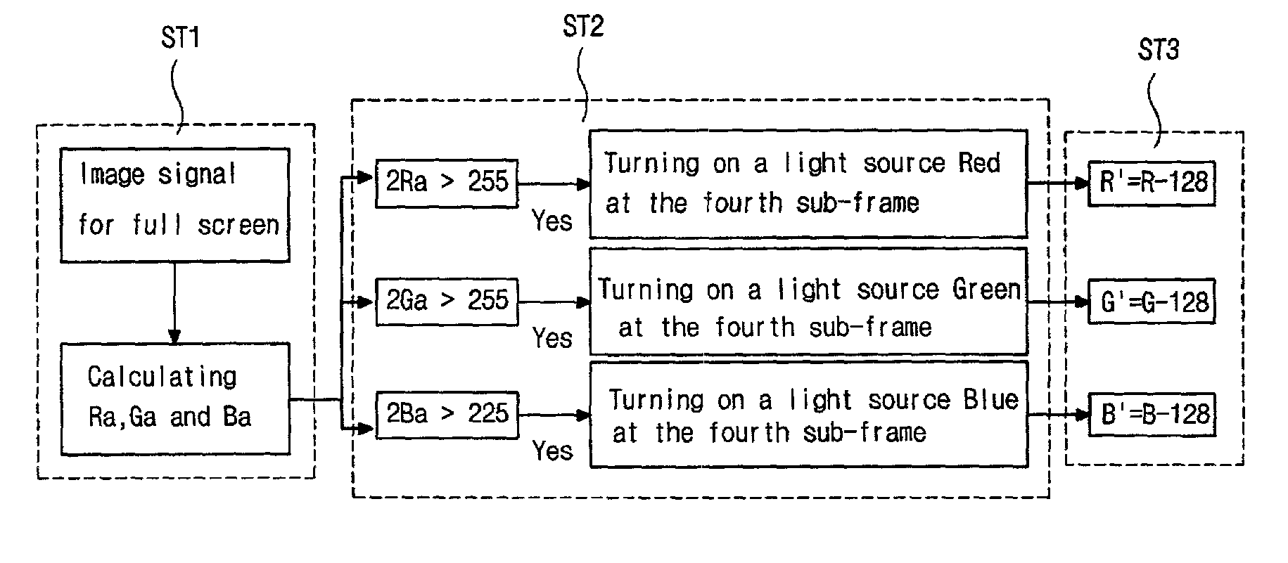
[0019]Another object of the present invention is to provide a color image display method for a field sequential liquid crystal display device including an image signal processor in which each of light sources Red, Green and Blue is driven sequentially for every divided area of a screen in order to compensate for low response time of a liquid crystal and accomplish fast driving of the field sequential liquid crystal display device.

Problems solved by technology

However, flat panel displays are increasingly beginning to be used because of their small depth dimensions, desirably low weight, and low power consumption.
But the conventional active-matrix liquid crystal display device has some problems.
First, the material used for the color filter is expensive and the methods for manufacturing the color filter require more material to be consumed in the manufacturing process, resulting in an increase in the manufacturing cost.
Second, the maximum value of a transmissivity of a material used for the color filter is 33%, so that a brighter back light needs to be used in order to display a color image effectively, which results in the increase of the power consumption.
On the other hand, when the color filter is thin the transmissivity can be raised but, the color properties will become poor.
Therefore, a manufacturing process having great precision is required for the color filter, which results in a decrease in production yield and an increase in the rate of inferior goods.
The field sequential liquid crystal display device has not been popular until recently because of poor response time.
The directly underlaid type back light is usually used for the image display device where the luminance is important and has a high power consumption because of its relatively big thickness and high ratio of diffusion.
If the response time tLC (94) is decreased, and thus an actual response time of the liquid crystal becomes longer than the assigned response time of the liquid crystal, the back light is driven before the proper alignment of the liquid crystal occur, causing screen color to not be uniform.

Method used


Image

  • Method of color image display for a field sequential liquid crystal display device
  • Method of color image display for a field sequential liquid crystal display device
  • Method of color image display for a field sequential liquid crystal display device

Examples


Embodiment Construction

[0042]Reference will now be made in detail to the preferred embodiment of the present invention, which is illustrated in the accompanying drawings.

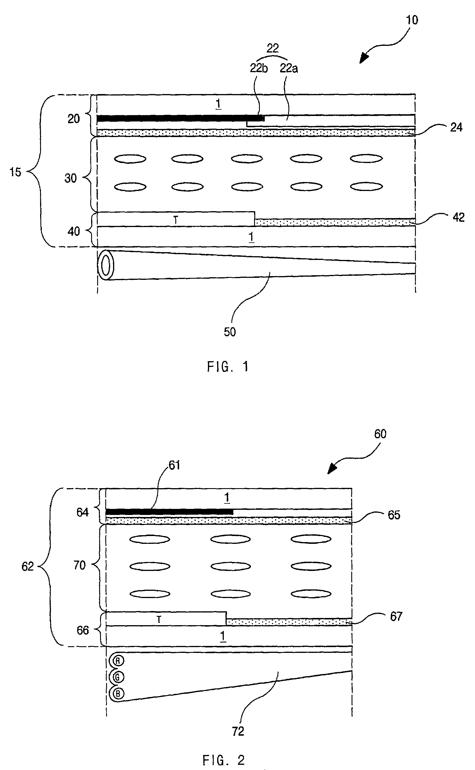
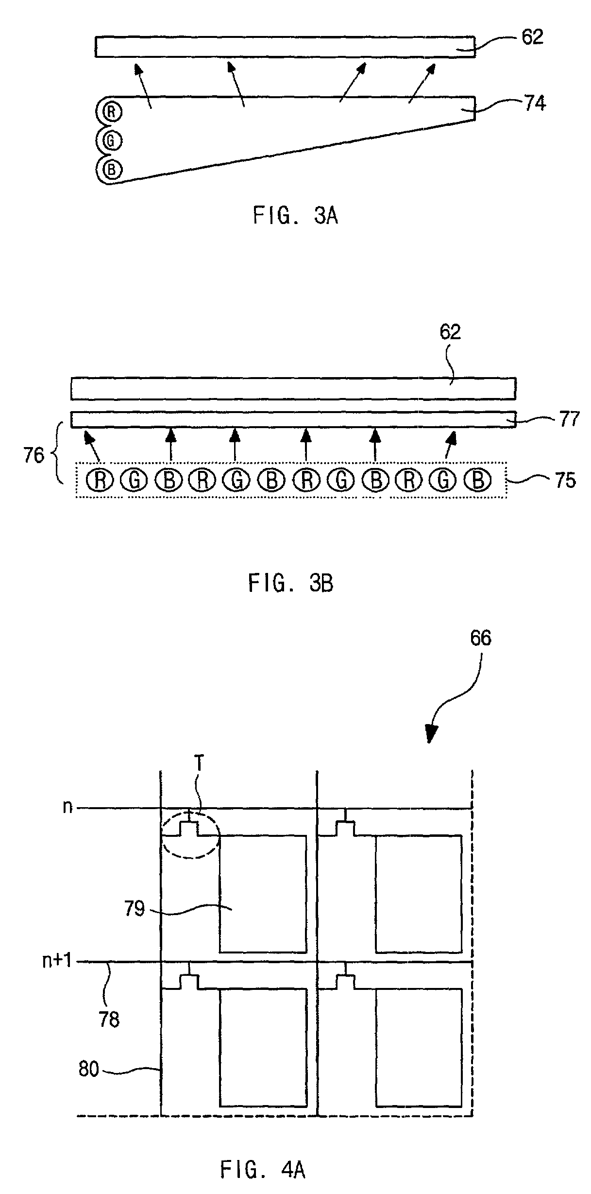
[0043]FIG. 7 is a schematic diagram illustrating a field sequential liquid crystal display device according to the present invention. The field sequential liquid crystal display device according to the present invention includes a liquid crystal panel 100 having an upper substrate and a lower substrate and liquid crystal layer disposed therebetween, a back light 110 having three light sources Red, Green and Blue and irradiating light to the liquid crystal panel 100, and an image signal processor 120 controlling a lighting speed of light sources Red, Green and Blue of the back light 110. The liquid crystal panel 100 and the back light 110 have a same structure as that of the conventional field sequential liquid crystal display device described before with respect to FIG. 2. One of Ferroelectric Liquid Crystal (FLC) mode, Optically Compensa...


PUM

PropertyMeasurementUnit
timeaaaaaaaaaa
timeaaaaaaaaaa
colorsaaaaaaaaaa

Abstract

A field sequential liquid crystal display device comprises a liquid crystal panel having an upper substrate, a lower substrate and a liquid crystal layer disposed therebetween, a back light disposed under the liquid crystal panel for irradiating a light to the liquid crystal panel and having 3 different light sources Red, Green and Blue sequentially driven; and an image signal processor controlling a lighting speed of each of the light sources Red, Green and Blue.A method of color image display for a field sequential liquid crystal display device including an image signal processor, comprises steps of dividing a frame into four sub-frames having a period of one-fourth of one frame period, driving each of light sources Red, Green and Blue sequentially at a first, a second and a third sub-frame, driving a light source combination with three or fewer colors of Red, Green and Blue at a fourth sub-frame, classifying each component R, G and B of a color image input signal using a gray level having 256 levels, deciding a maximum luminance value of the field sequential liquid crystal display device using the gray level, obtaining an average luminance value of each of component R, G and B from the image input signal, turning on one of light sources Red, Green and Blue having an average luminance value greater than the maximum luminance value at the fourth sub-frame, and converting the input luminance value of component R, G and B and an input luminance value of the fourth sub-frame using the image signal processor.Additionally, the method provides a time interval between driving sections of a previous light source and a next light source.

Description

[0001]This application claims the benefit of Korean Patent Application No. 2000-66450, filed on Nov. 9, 2000 in Korea, which is hereby incorporated by reference.BACKGROUND OF THE INVENTION[0002]1. Field of the Invention[0003]The present invention relates to an active-matrix liquid crystal display (AM LCD) device, and more particularly, to a field sequential liquid crystal display device and a method of color image display for the field sequential liquid crystal display device. Although the present invention is suitable for a wide scope of applications, it is particularly suitable for improving a field sequential liquid crystal display device leading to an increase of instantaneous luminance of specific color and a decrease of response time of a liquid crystal, for example.[0004]2. Discussion of the Related Art[0005]Until now, the cathode-ray tube (CRT) has been generally used for display systems. However, flat panel displays are increasingly beginning to be used because of their sma...

Claims


Application Information

Patent Timeline
Patent Type & Authority Patents(United States)
IPC IPC(8): G09G3/36G02F1/13357G02F1/133G09F9/00G09G3/20G09G3/34G09G5/02H04N9/30H04N9/31
CPCG09G3/3611G09G2310/0235G09G2300/0491G09G5/02G02F1/133
Inventor LIM, MOO-JONGHONG, HYUNG-KI
Owner LG DISPLAY CO LTD
Learn More