Image display device and image display method

a display device and liquid crystal technology, applied in the field of liquid crystal crystal type image display device, can solve the problems of degrading the image displayed, losing the true black image, and increasing the intensity of the backlight, so as to improve the dynamic contrast of the picture, eliminate the possibility of highlighting defective picture components, and high quality

Inactive Publication Date: 2006-05-30
SHARP KK
View PDF12 Cites 143 Cited by
  • Summary
  • Abstract
  • Description
  • Claims
  • Application Information

AI Technical Summary

Benefits of technology

[0028]According to embodiments of the present invention, no processing for widening a dynamic range of a picture signal is made, thereby eliminating the possibility of emphasizing defective picture components such as a defectively gradated portion and a noise of the picture signal.
[0029]Furthermore, according to embodiments of the present invention, since decision about the peak state of a picture to be displayed and information above representing a dark or bright scene ca

Problems solved by technology

However, the method of the document 1 for improving the display image quality by increasing the brightness of the backlight when the average brightness level of a picture signal is low involves the following problem.
The light leakage causes a phenomenon called “loss of true black” wh

Method used


Image

  • Image display device and image display method
  • Image display device and image display method
  • Image display device and image display method

Examples


first embodiment

(The First Embodiment)

[0050]Referring to FIGS. 1 to 5, an image display device according the first embodiment of the present invention is described as follows.

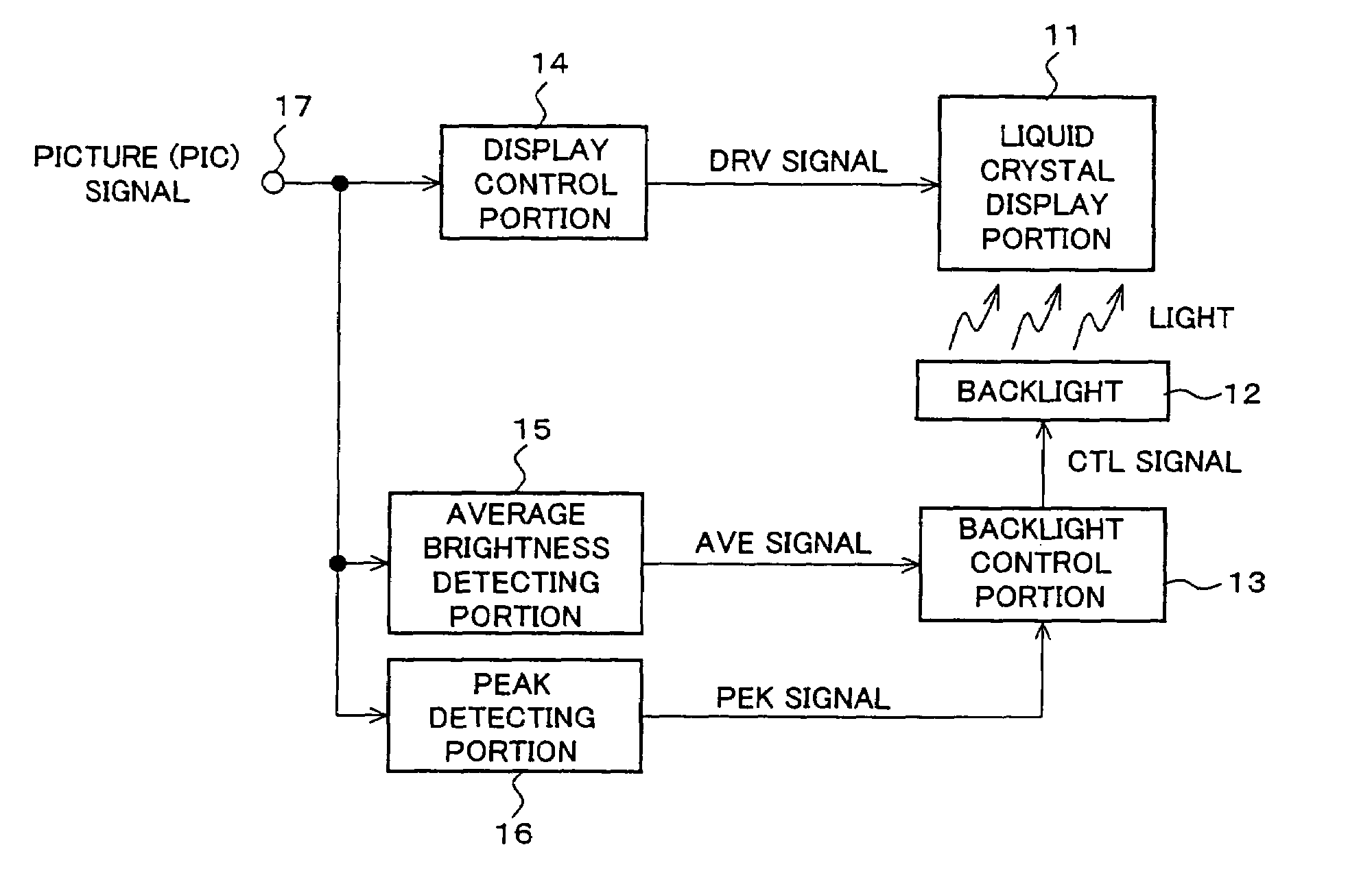
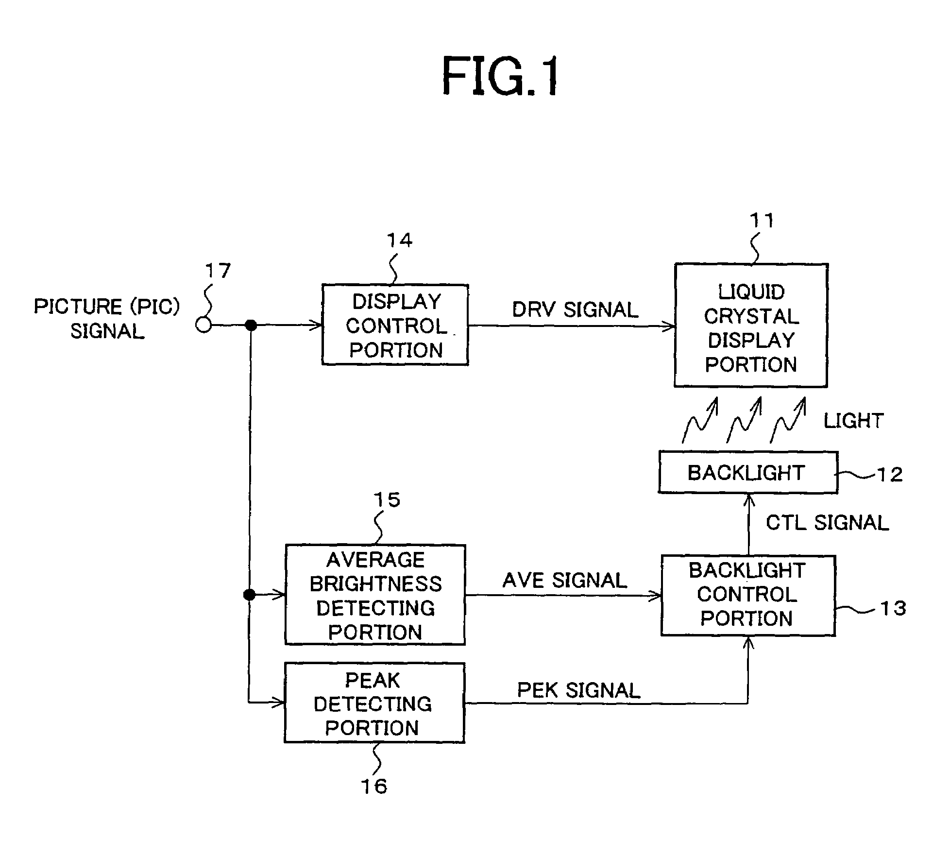
[0051]FIG. 1 is a construction block diagram of the image display device according to the first embodiment of the present invention, which comprises, as shown in FIG. 1, a liquid crystal display portion 11, a backlight 12, a backlight control portion 13, a display control portion 14, average brightness detecting portion 15, a peak detecting portion 16 and an input 17.

[0052]A PIC (Picture) signal in the form of, for example, a Y color difference signal to be displayed on the liquid crystal display portion 11 is inputted into the display device through the input 17. The display control portion 14 performs the control operation necessary for display the PIC signal on the liquid crystal display portion 11 and outputs it as a DRV (Drive) signal to the display portion. The backlight 12 serves a light source for providing the brightn...

second embodiment

(The Second Embodiment)

[0072]An image display device according to the second embodiment of the present invention will be described below with reference to FIGS. 6, 7A and 7B.

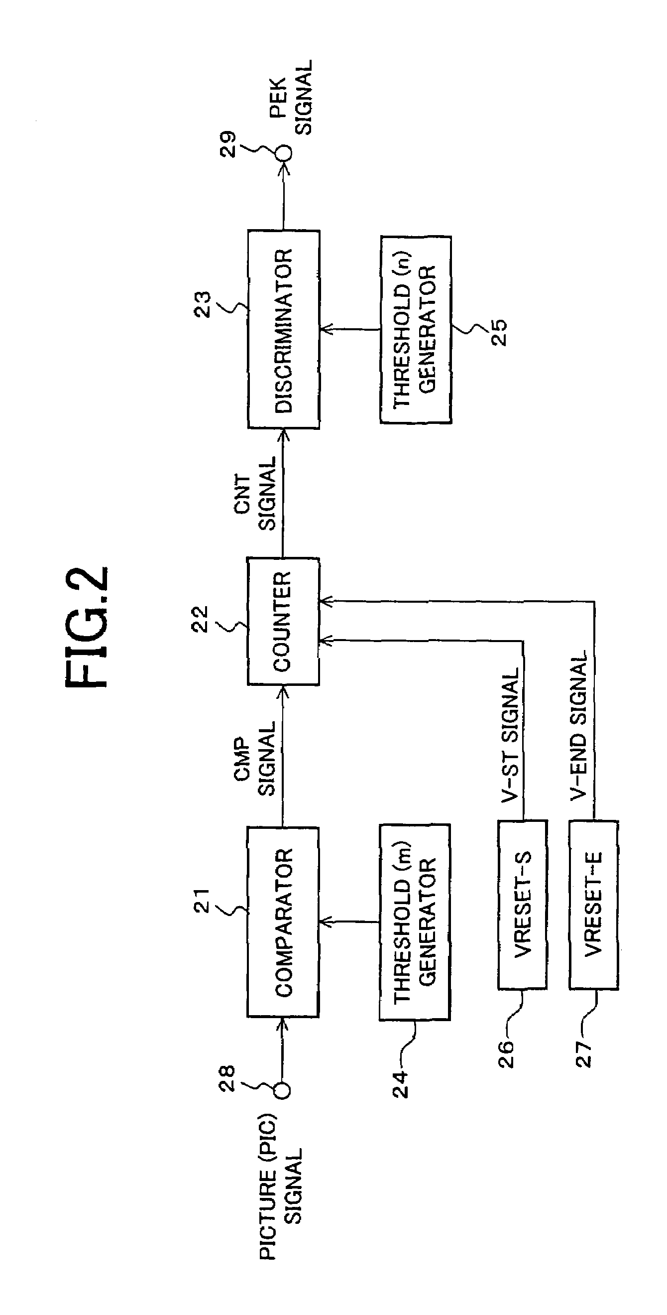
[0073]FIG. 6 is a block diagram of a peak detecting portion 16 of the display device which is the second embodiment of the present invention, where parts similar to those shown in FIG. 2 are given the same numerals. In FIG. 6, there are shown comparators 61, 62, 65, 66, counters 63, 64, a discriminator 67, threshold generators 68 to 71 for generating threshold values ma, mb, na and nb respectively and an output 72.

[0074]A PIC signal through the input 28 is input to the comparators 61 and 62 respectively. The comparator 61 compares each of successively inputted brightness signals or brightness components of the PIC signal with the threshold value ma generated by the threshold (ma) generator 68 and outputs a comparison result to the counter 63 which in turn counts inputs for a duration defined by V-ST signal and V...

third embodiment

(The Third Embodiment)

[0085]An image display device according to the third embodiment of the present invention will be described below with reference to FIG. 8.

[0086]FIG. 8 is a block diagram of a peak detecting portion 16 of the image display device which is the second embodiment of the present invention, where parts similar to those shown in FIG. 2 are given the same numerals. In FIG. 8, there are shown comparators 81 and 83, a latch 82 and a threshold (p) generator 84.

[0087]The shown embodiment is featured by the provision of the comparator 81 forming a loop to detect the maximum brightness level of an input PIC signal to be displayed. Specifically, a FBK (Feedback) signal indicating a comparison result is fed back to an input of the comparator 81. The feedback operation of the comparator 81 is conducted on each of successively inputted pixels of a PIC signal. The PIC signal and the FBK signal levels are compared with each other on the pixel-by-pixel basis and a larger signal is ...


PUM


Abstract

An image display device according to the present invention is capable of presenting to a viewer a high-quality lustrous video on a display screen with best screen brightness by increasing visual contrast and avoiding loss of true black elements without widening a dynamic range of a picture signal. The image display device is provided with a liquid crystal display portion (11), a display control portion (14), a backlight (12), a backlight control portion (13) and an average brightness detecting portion (15) and detects brightness of the light source in accordance with the average brightness of a picture signal to be displayed. It is further provided with a peak detecting portion (16) and corrects the control of the backlight control portion (13) in accordance with a detected peak value of a picture.

Description

FIELD OF THE INVENTION[0001]The present invention relates to a liquid crystal type image display device for displaying a picture signal on a liquid crystal display panel and more specifically to a transmission type liquid crystal display device of the direct viewing type or projection type, which has a light source and can dynamically adjust the luminance of the light source in accordance with a picture signal to be displayed.BACKGROUND OF THE INVENTION[0002]A liquid crystal display device represents a transmission type display device having a light source. The transmission type liquid crystal display device requires a separate light source since a liquid crystal panel itself does not emit light. A direct-viewing type liquid crystal display device has a light source called “back light” mounted behind the liquid crystal panel, which light source is usually a fluorescent lamp generally called a cold cathode tube. A projection type liquid crystal display device called generally a liqui...

Claims


Application Information

Patent Timeline
IPC IPC(8): G09G3/36G02F1/133G09G3/34
CPCG09G3/3406G02F1/13318G09G3/3611G09G2360/16G09G2320/0626G09G2320/066G09G2330/021G09G2320/0238
Inventor ITOH, HIROSHI
Owner SHARP KK
Why Eureka
Try Eureka