Self-calibrating beam profile ellipsometer

a self-calibrating, beam-profile technology, applied in the field of optical methods, can solve the problems of chromatic aberration, limit the reduction of measurement spot size, and is not always practical to reduce measurement siz

Inactive Publication Date: 2006-05-30
THERMA WAVE INC
View PDF23 Cites 16 Cited by
  • Summary
  • Abstract
  • Description
  • Claims
  • Application Information

AI Technical Summary

Problems solved by technology

At the same time, it is not always practical to reduce measurement size, particularly for ellipsometers.
Chromatic aberration is a second obstacle that often limits reductions in measurement spot sizes for ellipsometers.
Chromatic aberration results when an optical system transports light in a wavelength dependent fashion.
This problem arises because the optical components that direct the probe beam within an ellipsometer have their own ellipsometric parameters.
For BPE systems, separation is difficult to achieve because the objective lens is used for both illumination and imaging and must, as a result, be placed in close proximity to the sample.
In practice, this turns out to be a difficult goal to achieve.
One reason for this is the size and complexity of the high numerical aperture objective.
Mounting this lens in a stress free fashion is not generally possible.
Temperature fluctuations and air turbulence (often caused by wafer movements) induce additional stress on the objective.
This scheme, however, cannot be easily implemented to solve the objective effects.
There are two issues here: 1) the orientation of the stress changes as the environment perturbations are random in nature, and 2) even given the orientation of the stress, its effects can only be eliminated from the incident beam.
The process of characterization is expensive and time consuming (especially when repeated) and, in practice, may not be convenient or cost effective.
This not only reduces throughput, but also creates air turbulence during measurements.
Because the objective in BPE systems is highly sensitive to environment perturbations, these repeated wafer movements often lead to calibration errors.

Method used


Image

  • Self-calibrating beam profile ellipsometer
  • Self-calibrating beam profile ellipsometer
  • Self-calibrating beam profile ellipsometer

Examples


Embodiment Construction

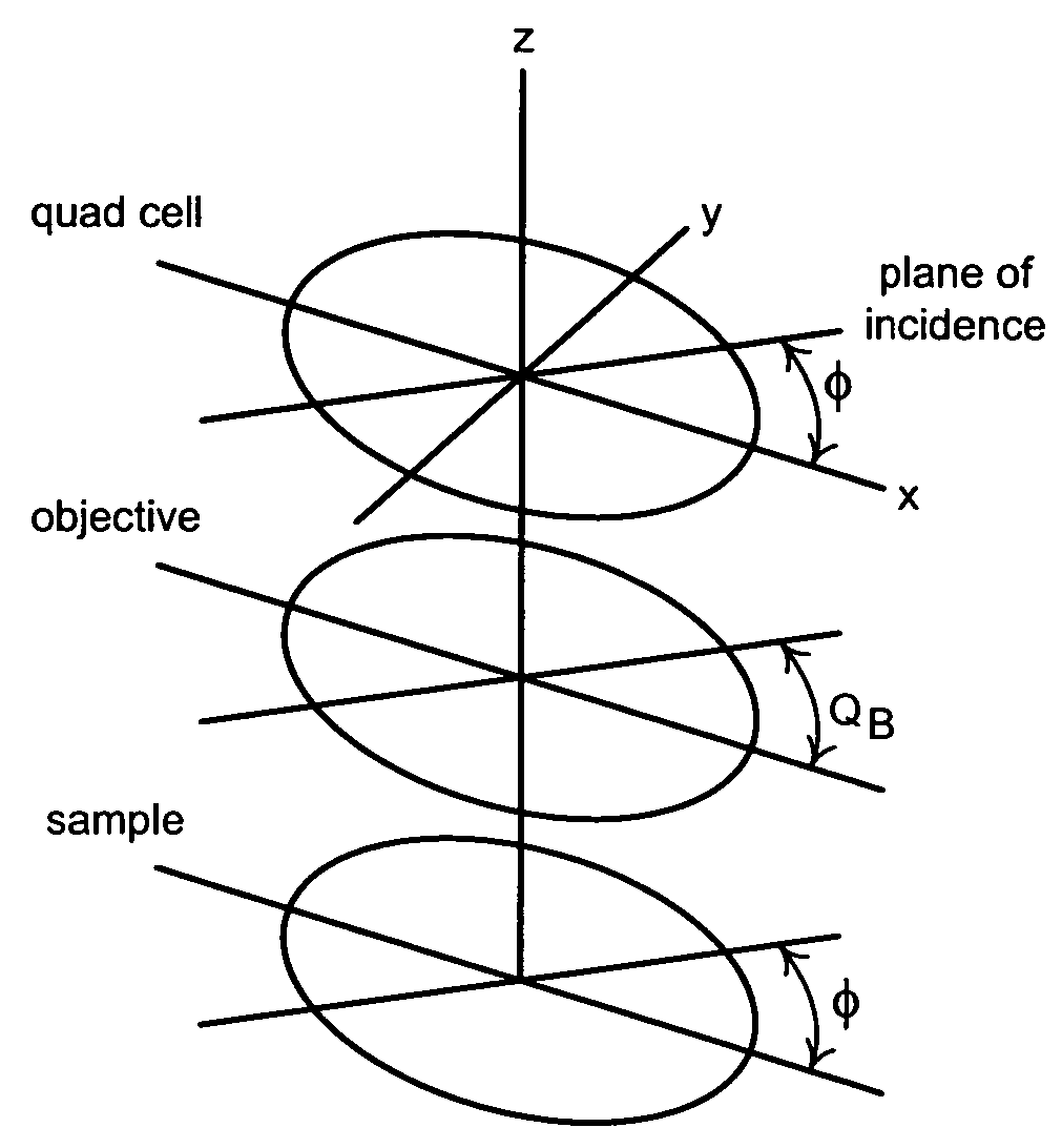
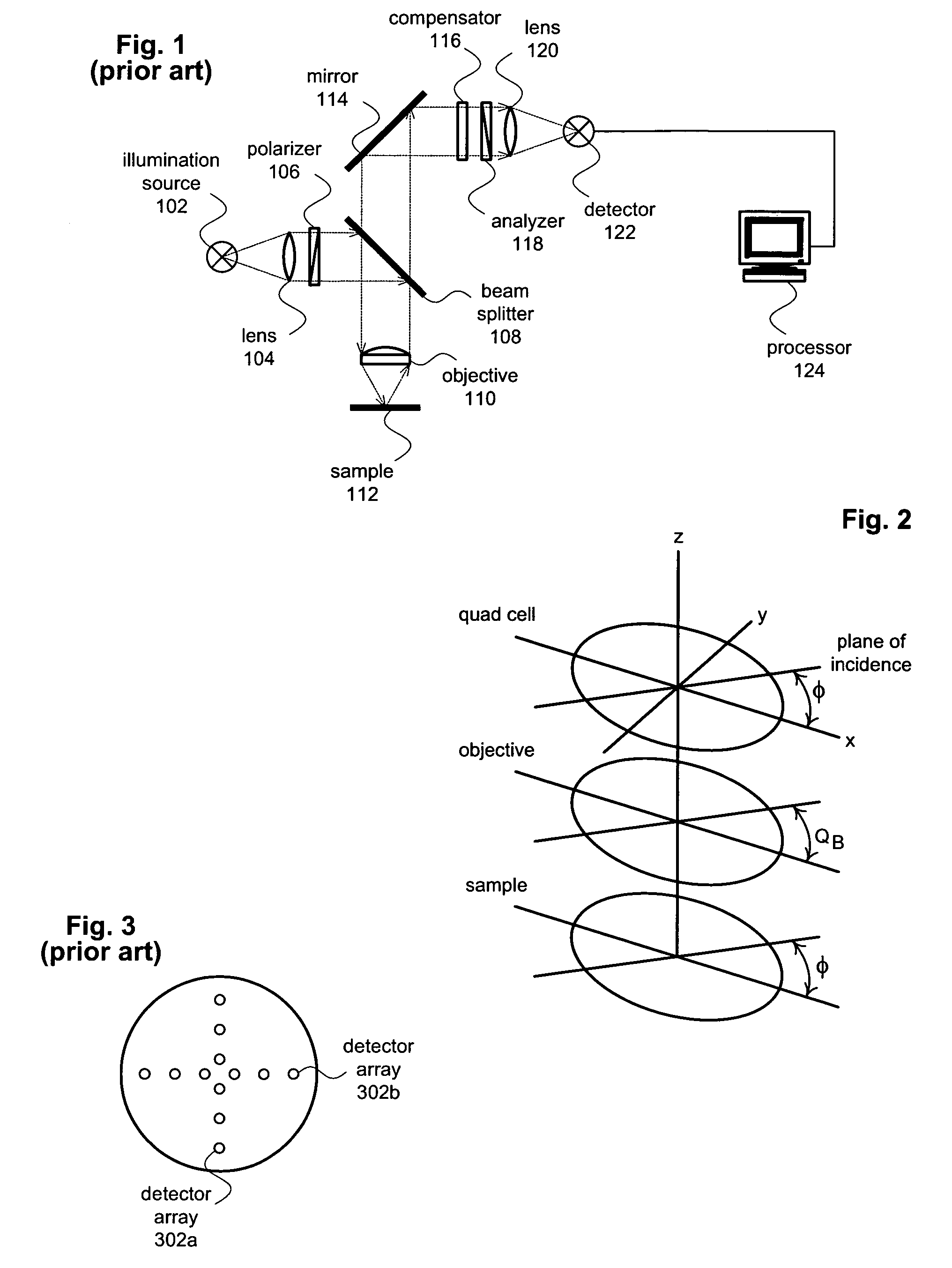
[0016]The present invention provides a real-time calibration method for beam profile ellipsometry systems. The calibration method increases ellipsometer accuracy by separating the ellipsometric parameters related to the sample from those related to the focusing optical elements. FIG. 1 shows an ellipsometer 100 suitable for use with the calibration method. As show in FIG. 1, ellipsometer 100 includes an illumination source 102 that produces a polychromatic or monochromatic probe beam. In some cases, illumination source will include one or more separate illumination sources that are combined or multiplexed in time to create the probe beam. After leaving illumination source 102, the probe beam is focused by a lens 104 and passed through a polarizer 106. Polarizer 106 imparts a known polarization state to the probe beam. Polarizer 106 may be, for example, a quartz Rochon prism, but in general the polarization does not necessarily have to be linear, or even complete. Polarizer 106 may b...


PUM

PropertyMeasurementUnit
angles of incidenceaaaaaaaaaa
azimuth angleaaaaaaaaaa

Abstract

A real-time calibration method for beam profile ellipsometry systems includes projecting an electromagnetic probe beam having a known polarization state though an objective lens onto the surface of a subject and collecting the reflected probe beam using the same objective. The reflected probe beam is then passed through a rotating compensator and analyzer before being received by a detector. A processor performs a harmonic analysis on the detector output to determine normalized Fourier coefficients. The processor uses Fourier coefficients to measure the retardation δB and the azimuth angle QB of the objective lens; and uses the retardation δB and the azimuth angle QB to identify the ellipsometric effects of the objective lens.

Description

PRIORITY[0001]This application claims priority from U.S. Provisional Application Ser. No. 60 / 471,915, filed May 20, 2003, the disclosure of which is incorporated herein by reference.TECHNICAL FIELD[0002]The subject invention relates generally to optical methods for inspecting and analyzing semiconductor wafers and other samples. In particular, the subject invention relates to methods for increasing the accuracy of an ellipsometer by separating the ellipsometric parameters related to the sample from those related to the focusing optical elements.BACKGROUND OF THE INVENTION[0003]As geometries continue to shrink, manufacturers have increasingly turned to optical techniques to perform non-destructive inspection and analysis of semiconductor wafers. Techniques of this type, known generally as optical metrology, operate by focusing an optical beam on a sample and then analyzing the reflected energy. Spectroscopic ellipsometer (SE) is a widely used form of optical metrology that is particu...

Claims


Application Information

Patent Timeline
Patent Type & Authority Patents(United States)
IPC IPC(8): G01N21/00G01J4/00
CPCG01J4/00
Inventor WANG, HAIMINGFANTON, JEFFREY T.WEI, LANHUA
Owner THERMA WAVE INC
Why Eureka
Try Eureka