
Heat dissipation device assembly with fan cover

a technology of heat dissipation device and fan cover, which is applied in the direction of lighting, heating apparatus, and semiconductor/solid-state device details, etc., can solve the problems of increasing the temperature of the cpu, increasing the heat generation, and inability to operate reliably, so as to reduce the dead space of airflow and increase the cooling performance

Inactive Publication Date: 2006-06-06
HON HAI PRECISION IND CO LTD
View PDF26 Cites 8 Cited by
  • Summary
  • Abstract
  • Description
  • Claims
  • Application Information

AI Technical Summary

Benefits of technology

The solution significantly improves cooling performance by ensuring airflow reaches the bottom portion of the heat sink, effectively removing accumulated heat and maintaining CPU temperature within a safe range.

Problems solved by technology

However, the faster the CPU runs, the more heat it generates.
Accumulation of heat at the CPU will lead to an increase of temperature of the CPU, which results in instablity of operation and even destroying the CPU.
Airflow provided by the fan 200 will escape from the conductive column during traveling downwardly, which leads to forming of dead space around the bottom portion of the conductive column through which little airflow pass.

Method used


Image

  • Heat dissipation device assembly with fan cover
  • Heat dissipation device assembly with fan cover
  • Heat dissipation device assembly with fan cover

Examples


second embodiment

[0023]In the above description of the preferred embodiment of the present invention, the slot 53 can also be constructed in other forms. FIG. 4 shows the present invention in which an alternative fan cover 501 is illustrated. The fan cover 501 is constructed around a central line 2—2 and defines a plurality of elongated slots 531 each of which extends between the first open end (not visible) of the fan cover 501 and the second open end 521 and is parallel to the central line 2—2. Each slot 531 has two opposite closed ends adjacent the respective first and second ends of the fan cover 501. The dimension of the slot 531 in the direction of the central line 2—2 is greater than that in the direction surrounding the central line 2—2. Alternatively, the slots 531 are angled to the central line 2—2 but substantially parallel to the channels formed between the radiation fins of the heat sink.

third embodiment

[0024]It is obvious that the fan 40 can be mounted to the fan cover 50 instead of the heat sink 30. Referring to FIG. 5, the present invention is illustrated. A fan 402 comprises a bracket 421 defining a plurality of parallel grooves 431 which are spaced with even intervals. An annular flange 523 for locating the fan 402 in the direction of the central line of the fan cover 50, and a plurality of ribs 525 substantially perpendicular to the flange 523 protrudes from the inner surface of the fan cover 502 at the second open end 522. The fan 402 is mounted to the fan cover 502 at the second open end 525 in a manner that the ribs 525 are received in the grooves 431.

[0025]Furthermore, the fan 40, 402 is not limited to locate inside the fan cover 50, 501, 502 under a condition that the fan 40, 402 is adjacent to one of open ends of the fan cover and is able to provide an airflow through the heat sink 30 housed in the fan cover 50, 501, 502. Please refer to FIG. 6, a fourth embodiment of t...


PUM


Abstract

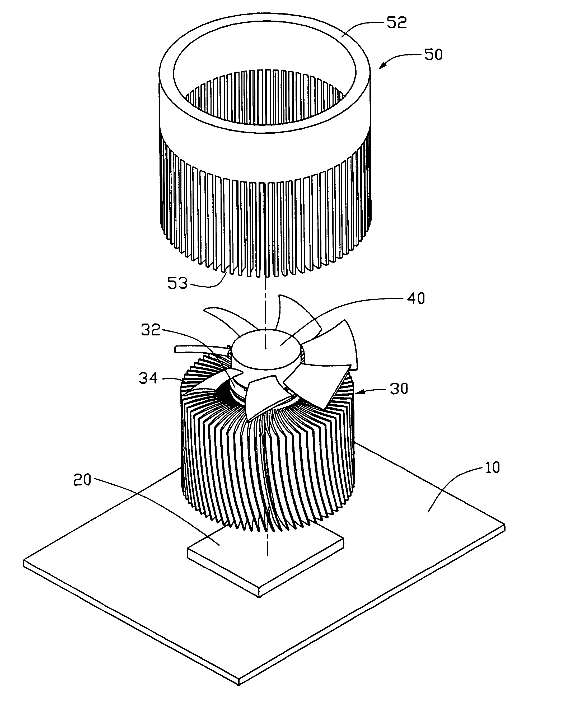
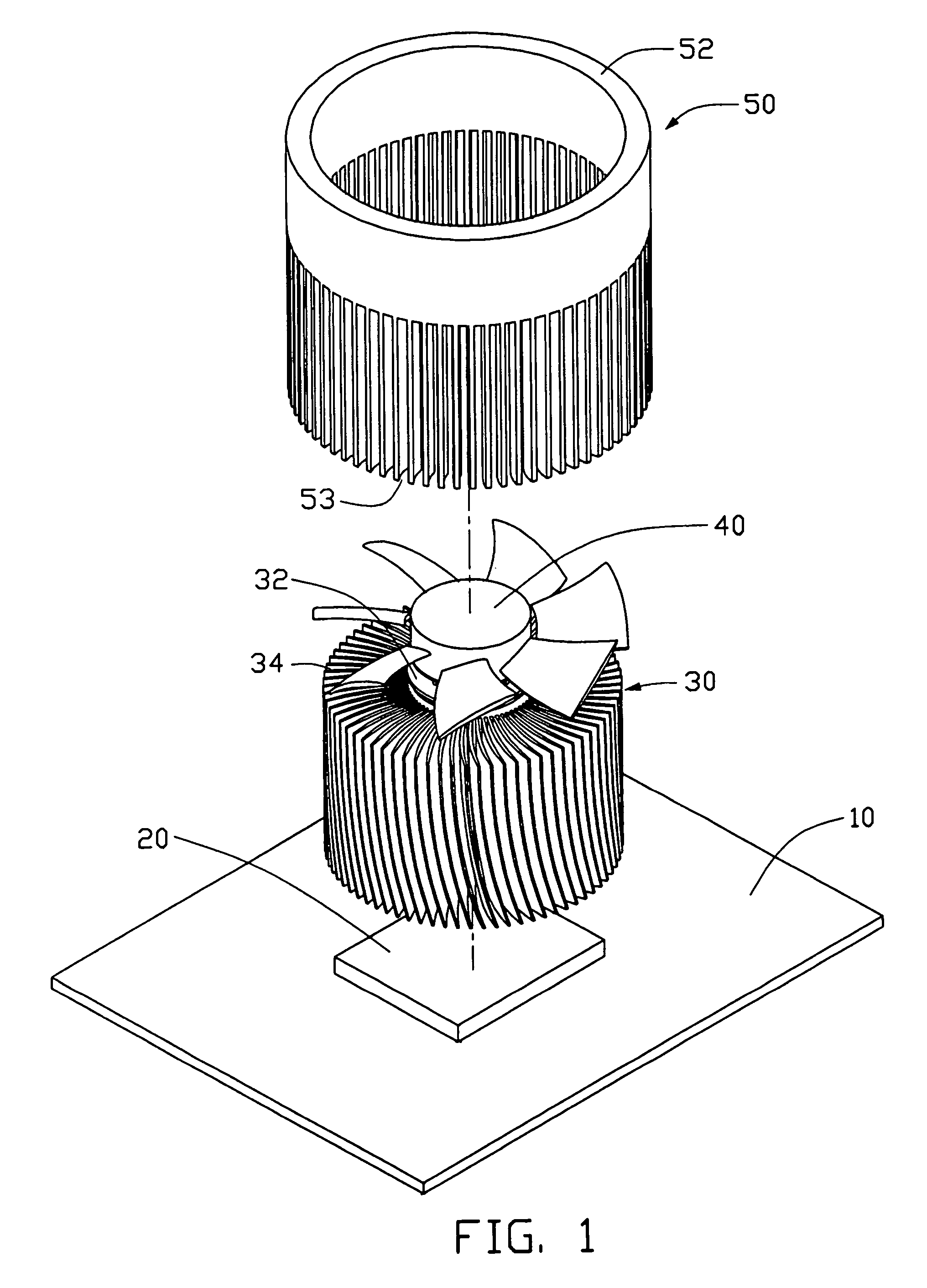
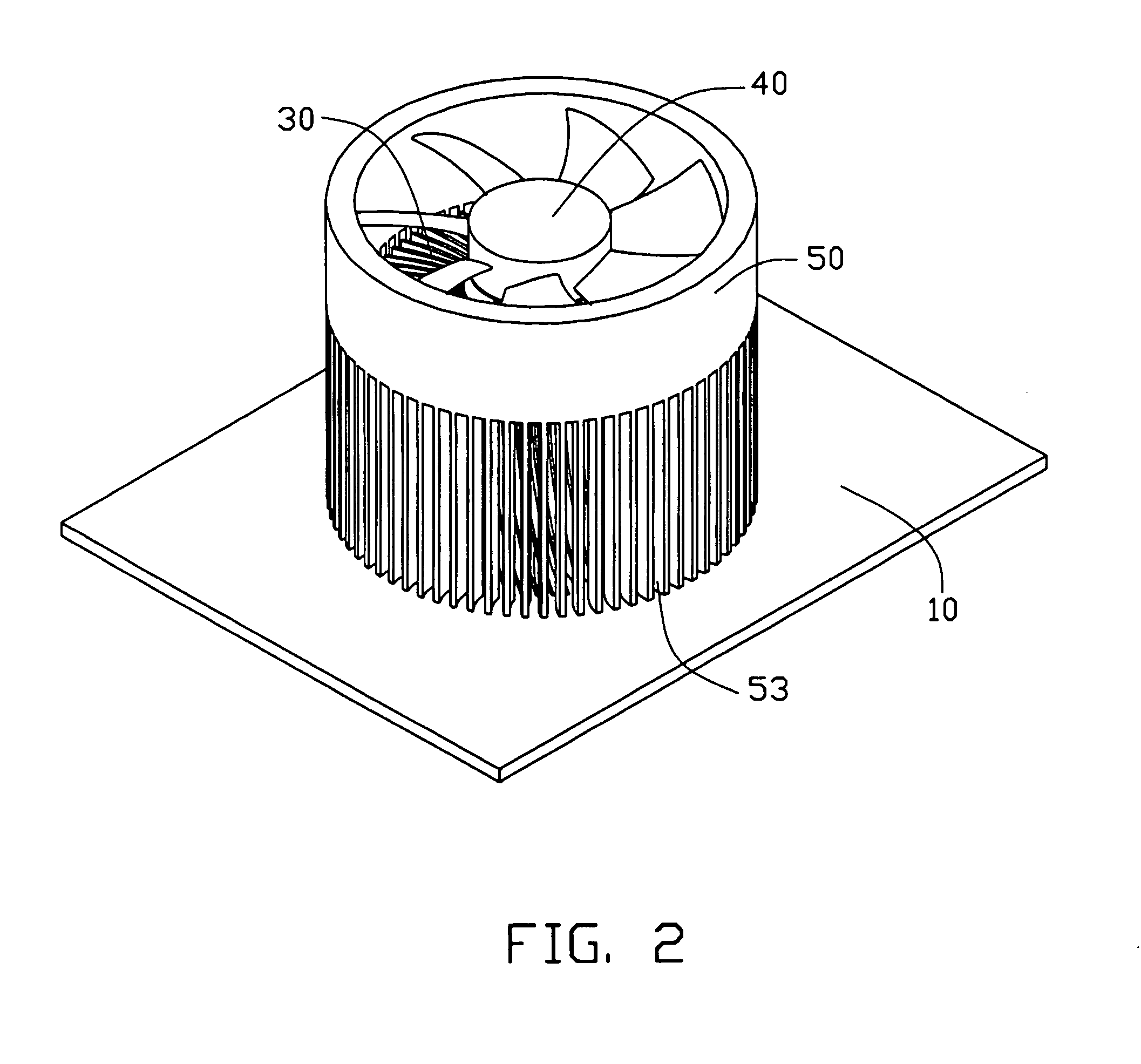
A heat dissipation device assembly comprises a heat sink having a columniform conductive core and a plurality of fins arranged radially around the conductive core, a columnar fan cover housing the heat sink and defining a first open end and a second open end, and a fan located at the second open end of the fan cover. Pluralities of channels are formed between the radiation fins. A plurality of elongated slot surrounding the heat sink is defined in the fan cover and extends from the first open end of the fan cover to the second open end. The airflow provided by the fan travels through the channels and the slots to outside of the fan cover.

Description

BACKGROUND OF THE INVENTION[0001]1. Field of the Invention[0002]The present invention relates generally to a heat dissipation device, and more particularly to an improved heat dissipation device assembly with a fan cover for rapidly dissipating heat generated by an electronic element package such as a Central Processing Unit (CPU).[0003]2. Related Art[0004]With the continuing and rapid development of integrated circuits technology, computer has been broadly applied in industry. Along with the increase of requirement of performance, the computer runs faster and faster. The speed of a computer is mainly determined by a CPU installed on a printed circuit board in the computer. Therefore, it is required that the CPU operates at a very high frequency. However, the faster the CPU runs, the more heat it generates. Accumulation of heat at the CPU will lead to an increase of temperature of the CPU, which results in instablity of operation and even destroying the CPU. So the heat must be remo...

Claims


Application Information

Patent Timeline
Patent Type & Authority Patents(United States)
IPC IPC(8): H05K7/20G06F1/20H01L23/34H01L23/467
CPCH01L23/467H01L2924/0002H01L2924/00
Inventor KU, CHIN-LONGYEH, CHIN-WEN
Owner HON HAI PRECISION IND CO LTD
Learn More