

Scratch masking coatings for optical substrates
a technology of optical substrates and scratching, which is applied in the direction of photomechanical equipment, instruments, record information storage, etc., can solve the problems of changing the intensity and colour of the reflected light from the coating, affecting the colour and intensity of the light reflected from the surface of the coating,
- Summary
- Abstract
- Description
- Claims
- Application Information
AI Technical Summary
Benefits of technology
Problems solved by technology
Method used
Image

Examples
example 1
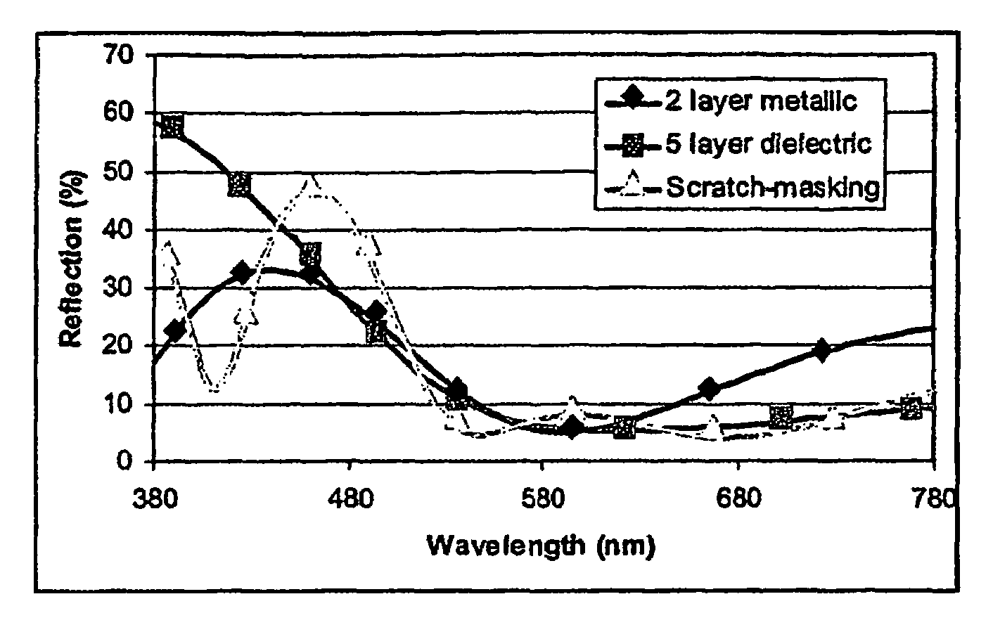
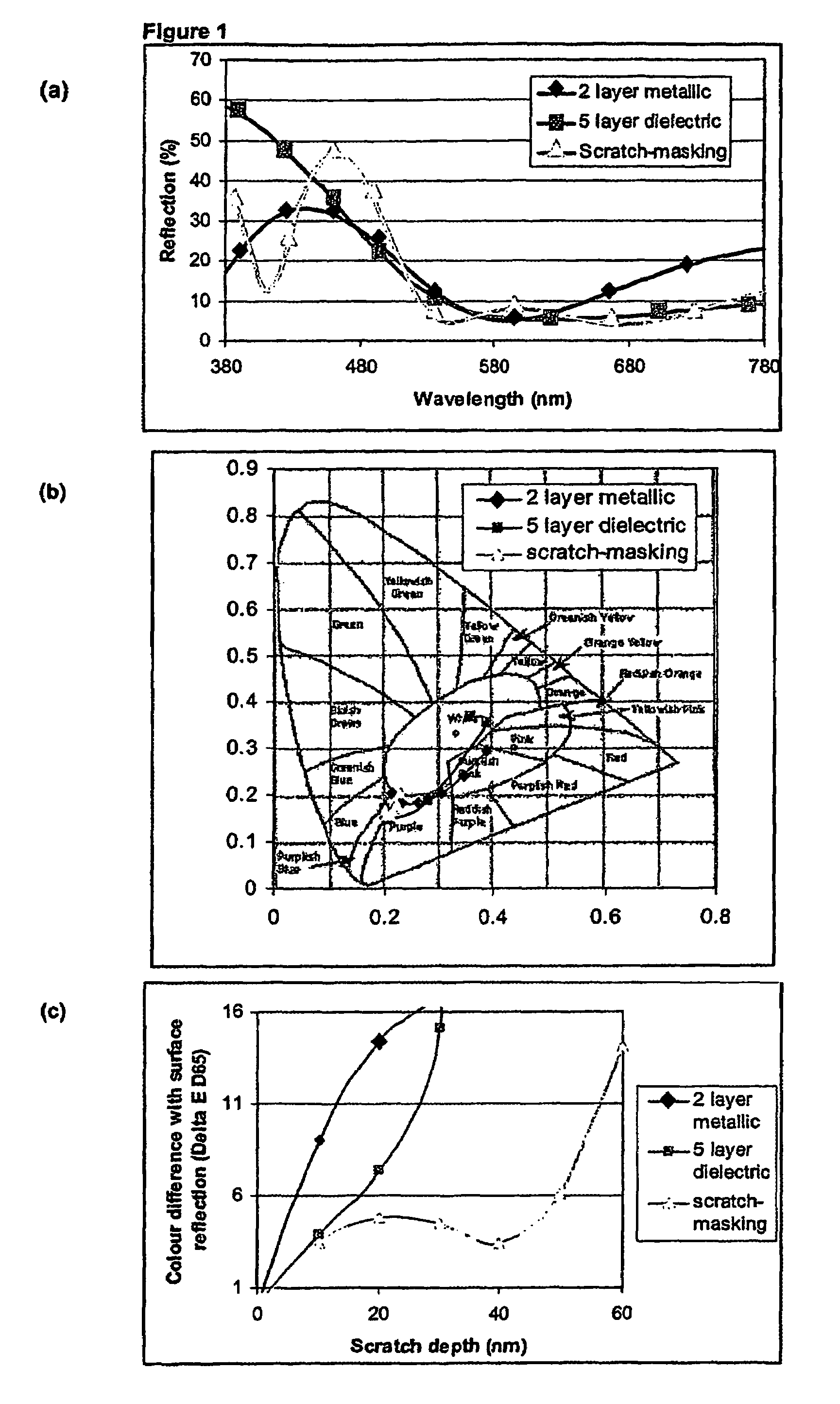
[0057]Table 1 illustrates an example of a scratch resistant, night blue reflective (mirror) coating and two comparative coatings with similar reflectance and colour characteristics (as determined using the CIE 1931 colour system). The first comparative coating is a two layer metallic coating. The second comparative coating is a five layer dielectric coating.
[0058]The properties of each of the coatings is as calculated using the commercial software package Tfcalc (Thin Film Design software by Software Spectra Inc, Portland Oreg., USA).
[0059]
TABLE 12 layer5 layerScratch -Thickness (nm)metallicdielectricmaskingCr500SiO22952420Material with05037n = 2.09@550 nmSiO205157Material with032178n = 2.09@550 nmTop SiO2020317R (%)10.69.99.9x (CIE1931)0.2130.2010.201y (CIE 1931)0.2030.1670.169The term “R” represents the predicted percentage luminosity of the light reflected from the coating. Values x and y represent predicted chromaticity coordinates of the reflected light according to the CIE 193...
example 2
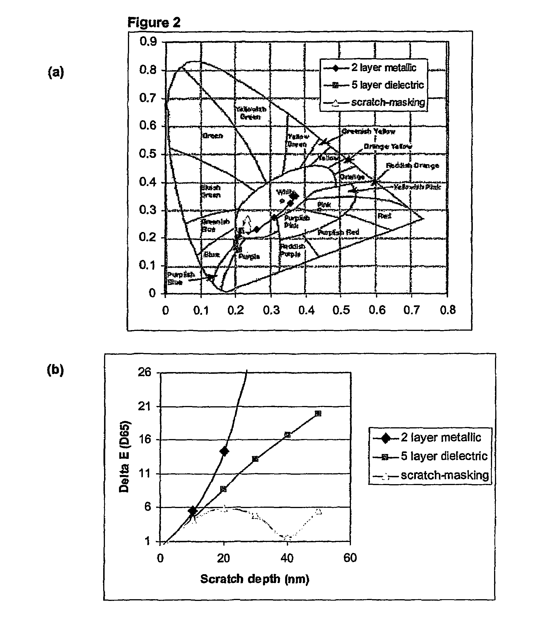
[0065]Table 2 illustrates an example of a scratch resistant, sky blue reflective (mirror) coating and two comparative coatings with similar reflectance and colour characteristics (as determined using the CIE 1931 system of colour specification). The first comparative coating is a two layer metallic coating. The second comparative coating is a five layer dielectric coating.
[0066]The properties of each of the coatings is as calculated using the commercial software package Tfcalc (Thin Film Design software by Software Spectra Inc, Portland Oreg., USA).
[0067]
TABLE 22 layer5 layerScratch -Thickness (nm)metallicdielectricmaskingCr500SiO21007348.2Material with039.9164.8n = 2.09 @ 550 nmSiO2075.3117.3Material with014.6146.6N = 2.09 @ 550 nmTop SiO2069327.7R (%)7.614.414.4x (CIE1931)0.2350.2300.230y (CIE 1931)0.2230.2490.250The term “R” represents the predicted percentage luminosity of the light reflected from the coating. Values x and y represent predicted chromaticity coordinates of the re...
example 3
[0072]Table 3 illustrates an example of a scratch resistant, black reflective (mirror) coating and two comparative coatings with similar reflectance and colour characteristics (as determined using the CIE 1931 system of colour specification). The first comparative coating is a two layer metallic coating. The second comparative coating is a, five layer dielectric coating.
[0073]The properties of each of the coatings is as calculated using the commercial software package Tfcalc (Thin Film Design software by Software Spectra Inc, Portland Oreg., USA).
[0074]
TABLE 32 layer5 layerScratch -Thickness (nm)metallicdielectricmaskingCr500SiO270050Material with017.810n = 2.09@550 nmSiO2039.654.9Material with050.925.2n = 2.09@550 nmTop SiO2018721.7R (%)7.615.613.4x (CIE1931)0.3550.3070.323y (CIE 1931)0.3250.3160.320The term “R” represents the predicted percentage luminosity of the light reflected from the coating. Values x and y represent predicted chromaticity coordinates of the reflected light a...
PUM
| Property | Measurement | Unit |
|---|---|---|
| refractive index | aaaaa | aaaaa |
| refractive index | aaaaa | aaaaa |
| refractive index | aaaaa | aaaaa |
Abstract
Description
Claims
Application Information