Apparatus for testing a light emitting device, and a method for testing light emitting devices

a technology for light emitting devices and apparatus, applied in electrical apparatus, lighting and heating apparatus, photoelectric discharge tubes, etc., can solve problems such as failure leds being overlooked by operators, visual verification of leds is far from error-proof, and visual inspection tends to be relatively slow

Inactive Publication Date: 2006-06-06
VIVEEN
View PDF3 Cites 30 Cited by
  • Summary
  • Abstract
  • Description
  • Claims
  • Application Information

AI Technical Summary

Problems solved by technology

Such visual verification of LEDs is far from error-proof.
Firstly, a failed LED may be overlooked by an operator due to operator fatigue.
Additionally, an operator can confuse a LED of one colour for that of another colour, again as a result of operator fatigue.
Additionally, visual inspection tends to be relatively slow since the operational characteristics and colour of the LEDs must be individually inspected, and thus sequentially inspected which tends to be a relatively slow and time consuming process.
However, such automatic vision testing systems tend to be relatively expensive, relatively large and unwieldy.
Additionally, since the image of the printed circuit board grabbed from the video camera contains a significant amo

Method used


Image

  • Apparatus for testing a light emitting device, and a method for testing light emitting devices
  • Apparatus for testing a light emitting device, and a method for testing light emitting devices
  • Apparatus for testing a light emitting device, and a method for testing light emitting devices

Examples


Embodiment Construction

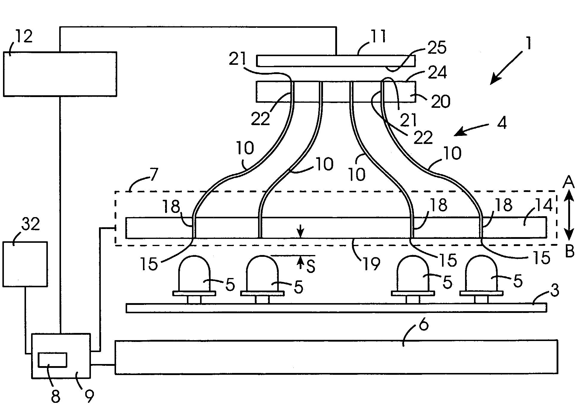
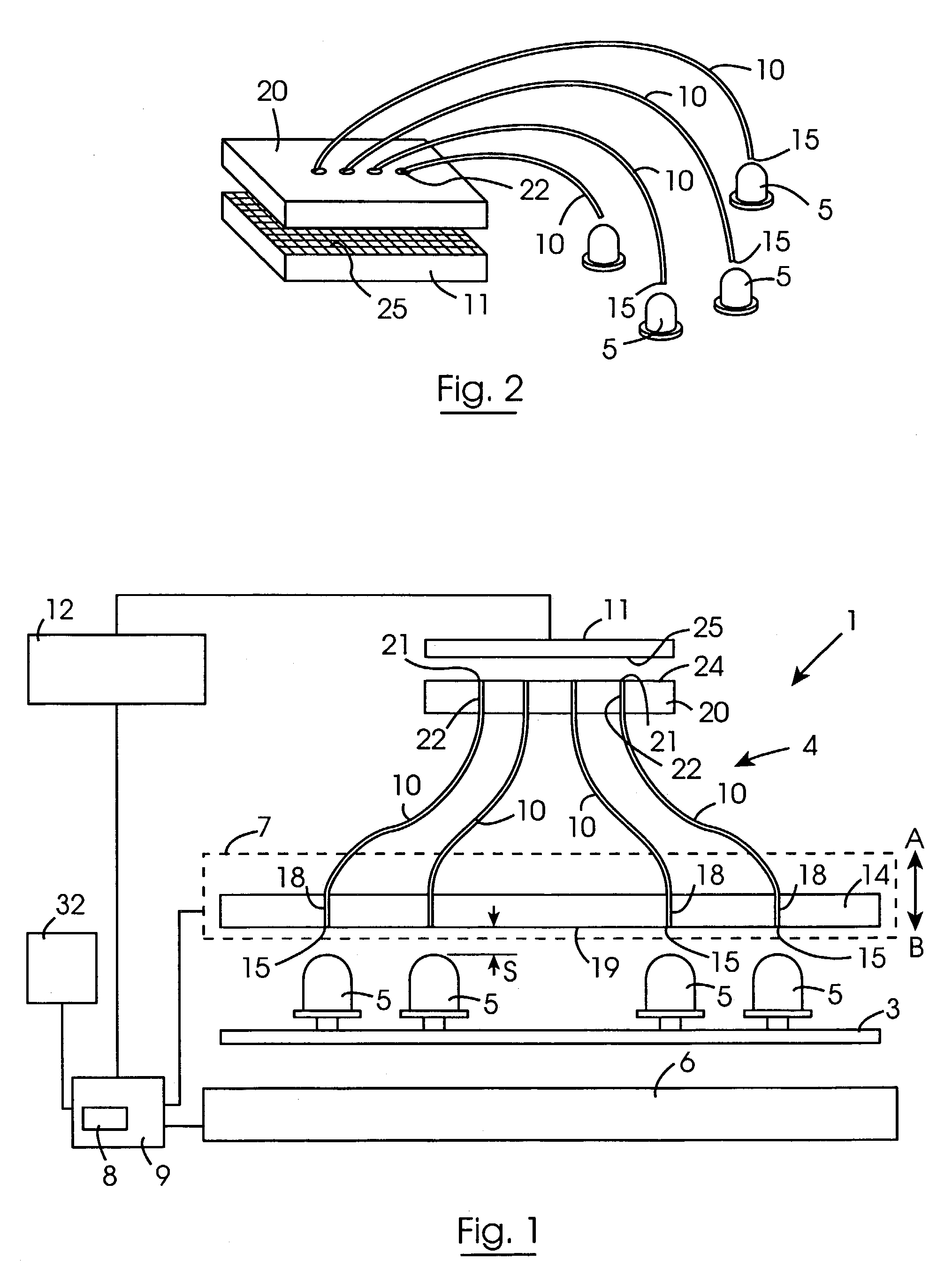
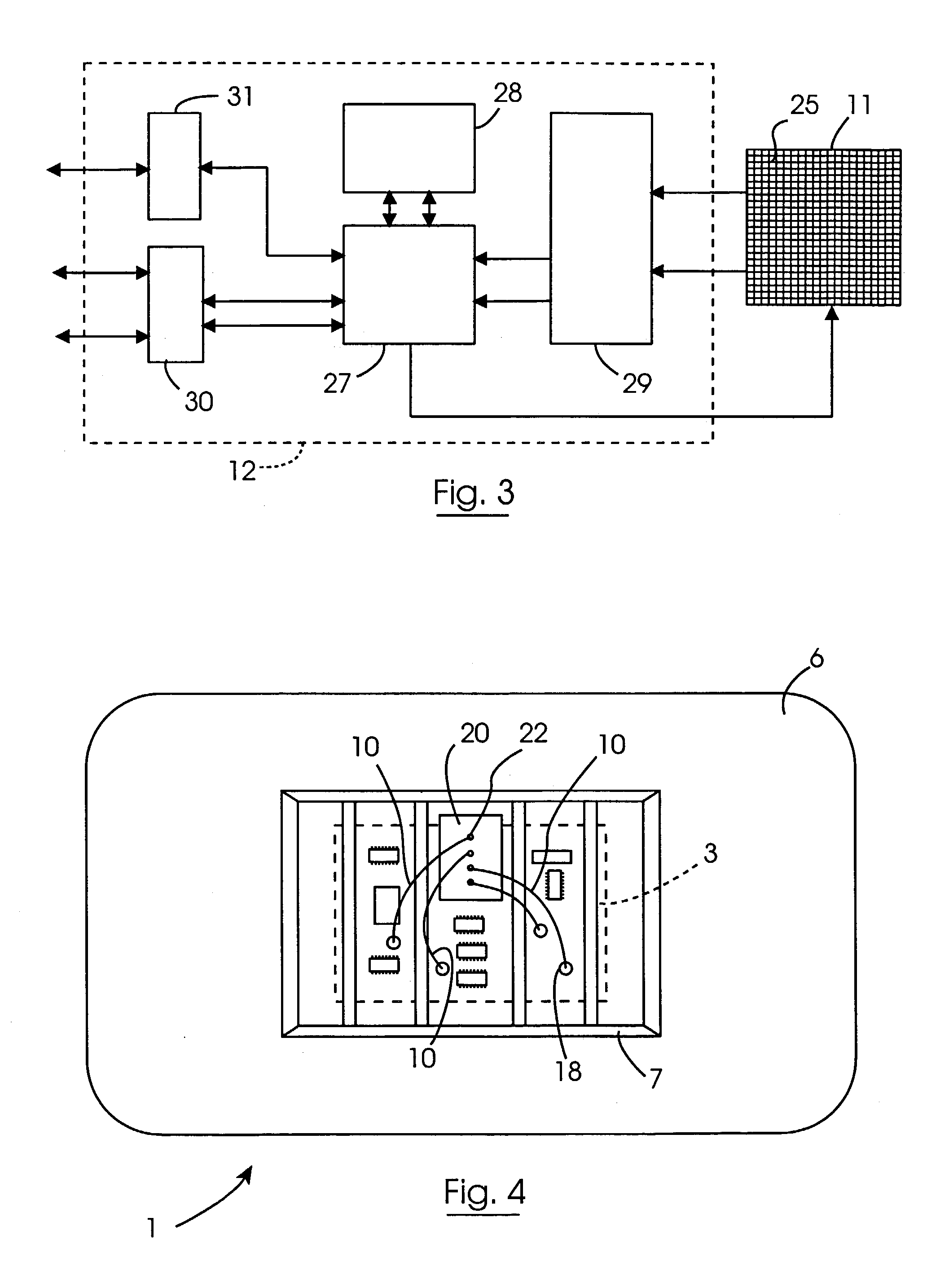
[0047]Referring to the drawings and initially to FIGS. 1 to 4 there is illustrated a test fixture according to the invention indicated generally by the reference numeral 1 for testing printed circuit boards 3. The test fixture 1 comprises apparatus also according to the invention which is indicated generally by the reference numeral 4 for testing LEDs 5 of the printed circuit boards 3, and for verifying if the LEDs 5 are emitting light and if the emitted light from the respective LEDs 5 is of the correct colour and brightness. The test fixture 1 comprises a base 6 for sequentially receiving the printed circuit boards 3. Locating pins (not shown) are provided extending upwardly from the base 6 for engaging corresponding bores (not shown) in the printed circuit boards 3 for locating and aligning the printed circuit board 3 on the base 6. Guide pins (also not shown) extending upwardly from the base 6 slideably engage corresponding bushed bores (also not shown) in a mounting frame 7 for...


PUM


Abstract

A text fixture (1) comprises apparatus (4) for verifying the color and brightness of light emitted from LEDs (5) of a printed circuit board (3). A base (6) of the fixture (1) supports the printed circuit board (3) during testing. A mounting panel (14) locates ends (15) of a plurality of optical fibers (10) adjacent the LEDs (5) on the printed circuit board (3), and ends (21) of ht optical fibers (10) are terminated in a terminating panel (20) adjacent an image sensing panel (11). The image sensing panel (11) comprises an array of individually addressable light and color sensitive pixels (25) onto which light from the optical fibers (10) is incident. An analysing circuit (12) scans the pixels (25) for determining the brightness values and the tristimulus values of the incident light, and a control circuit (9) compares the tristimulus values and brightness values with reference tristimulus and brightness values for verifying the color and brightness of the light emitted by the respective LEDs (5).

Description

[0001]This is a National Stage entry under 35 U.S.C. § 371 of Application No. PCT / IE01 / 00055 filed Apr. 27, 2001; the above noted prior applications are all hereby incorporated by reference.[0002]The present invention relates to apparatus for testing at least one light emitting device on a panel, for example, one or more light emitting diodes (LEDs) on a printed circuit board, and in particular, the invention relates to such apparatus for verifying if the colour of light being emitted by the light emitting device is of the correct colour. The invention also relates to a method for testing a light emitting device.[0003]Printed circuit boards, for use in computers, and other electronic assemblies include many LEDs and in general the LEDs are of different colour for signifying different operational aspects of the circuits of printed circuit board. For example, the LEDs may emit light in the red spectrum, the yellow spectrum, the green spectrum, the blue spectrum, and indeed, any other ...

Claims


Application Information

Patent Timeline
IPC IPC(8): H01L27/00F21V7/04B60Q1/00H05K13/08
CPCG01R31/2635H05K13/08G01J3/50G01J1/0425G01J1/42G01J2001/4252
Inventor HUSSEY, CONLETH DENISOAKLEY, KENNETH PETERCROWLEY, MICHAELO'TOOLE, EAMONNDAVERN, TIMOTHY
Owner VIVEEN
Why Eureka
Try Eureka