Structures, systems and methods for joining articles and materials and uses therefor

Active Publication Date: 2006-06-06
NANOSYS INC
View PDF67 Cites 123 Cited by
  • Summary
  • Abstract
  • Description
  • Claims
  • Application Information

AI Technical Summary

Benefits of technology

[0010]Furthermore, in yet other embodiments, the nanofibers are composed of the same material as one or more of the first or second substrates. Other embodiments include where the nanofibers are hollow nanotubular structures. In yet other embodiments substantially all nanofibers comprise one or more associated moiety (optionally a coating composed of the one or more associated moiety) which can be a functional moiety in some embodiments. In some such embodiments the functional moiety can increase van der Waals attraction between the nanofiber and the at least second surface (i.e., so that the attraction between the nanofiber and the second surface is greater than the van der Waals attraction between the nanofiber and the at least second surface in the absence of the moiety) or can increase friction forces between the nanofiber and the at least seco

Problems solved by technology

While such typical adhesives are quite useful, they do have a number of limitations.
For example, the layer of adhesive necessary to join surfaces can be inconveniently thick (e.g., from hundreds of microns to millimeters, etc.).
While that might be acceptable in some situations, it is quite inappropriate in others.
Adhesives can also often leave messy residues.
Additionally, adhesives can leak, spread or volatilize from their area of application into other nearby areas where they are not desired.
Such spreading can not only r

Method used


Image

  • Structures, systems and methods for joining articles and materials and uses therefor
  • Structures, systems and methods for joining articles and materials and uses therefor
  • Structures, systems and methods for joining articles and materials and uses therefor

Examples


example 1

Construction of an Adherent Nanofiber Substrate

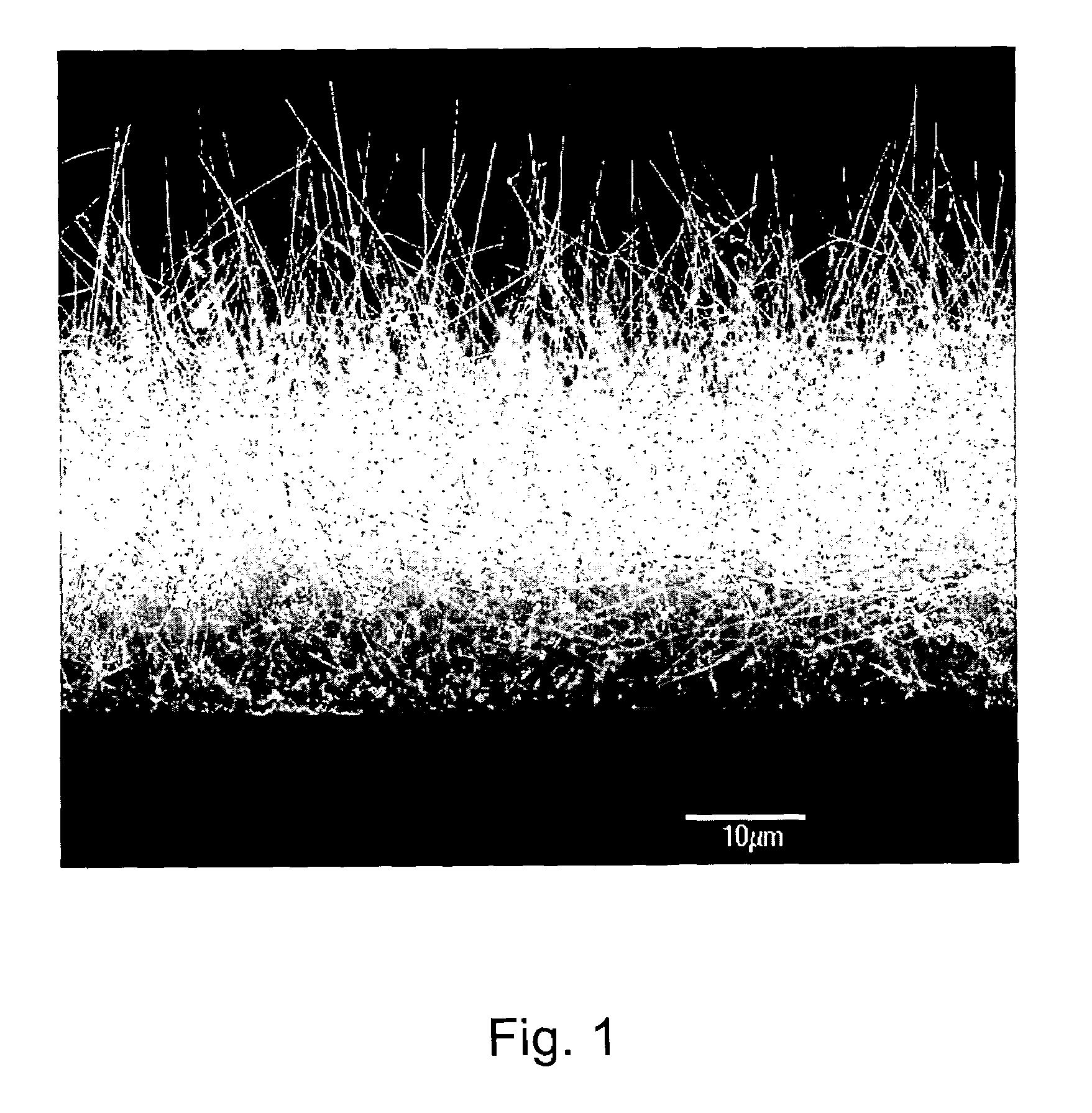
[0095]Silicon nanofibers of approximately 40 nanometer in diameter and 50 um in length were grown on a four inch silicon wafer through a standard CVD process using gold colloids (see, e.g., above). The fiber density was approximately 2 nanofibers per square micron. To test the adhesion ability of the silicon nanofiber wafer, a microscope slide was suspended in a vertical orientation above a lab bench. A 2 centimeter×1 centimeter piece from the above silicon wafer containing the nanofibers was lightly pressed against the glass slide (with the nanofiber surface touching the glass slide). Thus, the top centimeter of the nanofiber wafer was exposed to the glass while the other centimeter was not in contact with the glass. A 200 gram weight was then attached to the free end of the silicon wafer via a binder clip. The weight was allowed to hang freely, thus, exerting a stress of 2 newtons on the nanofiber / glass interface. There was no measura...

example 2

Construction of an adherent nanofiber substrate

[0096]Silicon nanofibers of approximately 40 nanometer in diameter and 50 um in length were grown on a 4 inch silicon wafer by the standard CVD process using gold colloids. See, e.g., above. The fiber density was approximately 2 nanofibers per square micron. To test the adhesion ability of the silicon nanofiber wafer to itself, two 2×1 centimeter pieces were cut from the silicon wafer containing the nanofibers. One centimeter of the fiber surface of each piece was lightly pressed together. One free end of the pressed pieces was clamped in a vice on a ring stand and a 100 gram weight was hung from the opposite end. The weight was allowed to hang freely, thus, exerting a stress of 1 newton on the nanofiber surface / nanofiber surface interface. There was no measurable movement in the nanofiber joints in 10 days.

example 3

Reuse of Adherent Nanofiber Substrates

[0097]The nanofiber substrate in Example 1 was pulled away from the glass in a perpendicular direction. It was then pressed against a second suspended piece of glass and through a similar process was shown to again hold 2 newtons of force.


PUM

PropertyMeasurementUnit
Pressureaaaaaaaaaa
Pressureaaaaaaaaaa
Pressureaaaaaaaaaa

Abstract

This invention provides novel nanofibers and nanofiber structures which posses adherent properties, as well as the use of such nanofibers and nanofiber comprising structures in the coupling and/or joining together of articles or materials.

Description

CROSS-REFERENCE TO RELATED APPLICATIONS[0001]This application claims the benefit of U.S. Provisional Application No. 60 / 463,766 filed Apr. 17, 2003, entitled “STRUCTURES, SYSTEMS AND METHODS FOR JOINING ARTICLES AND MATERIALS AND USES THEREFOR.” This prior application is hereby incorporated by reference in its entirety.FIELD OF THE INVENTION[0002]The invention relates primarily to the field of nanotechnology. More specifically, the invention pertains to nanofibers and nanofiber structures which posses adherent properties, as well as to the use of such nanofibers and nanofiber comprising structures in the coupling and / or joining together of articles or materials.BACKGROUND OF THE INVENTION[0003]Joining together of articles and / or materials has been common for at least thousands of years. Such joining has typically been achieved through use of adhesives of various types, e.g., exogenous substances applied between articles or materials to be joined which adhere to both of the articles ...

Claims


Application Information

Patent Timeline
IPC IPC(8): B32B5/16B32B37/00C09J5/00C09J7/00
CPCA61B17/00B81C3/008C09J5/00C09J7/00H01L23/373Y10T428/2922B82Y30/00C09J2201/626C09J2400/123H01L2924/09701Y10S977/962Y10S977/902Y10S977/762Y10S977/931Y10S977/963Y10S977/766H01L2924/0002A61B17/00491Y10T428/24008Y10T428/2913Y10T156/10Y10T428/26Y10T428/2925H01L2924/00Y10T428/23993C09J2301/31
Inventor DUBROW, ROBERT
Owner NANOSYS INC
Why Eureka
Try Eureka