Low emissivity, high reflectivity insulation

a high reflectivity, low emissivity technology, applied in the direction of household objects, packaging goods, applications, etc., can solve the problem that the performance of thermal conductivity measurements made in the completely dry state in the laboratory cannot match the performance of a similar insulation under actual field conditions, and the difference in the rate of radiation flow between these two objects is dramatic, so as to reduce thermal losses

Inactive Publication Date: 2006-06-06
KRONA INDS
View PDF9 Cites 14 Cited by
  • Summary
  • Abstract
  • Description
  • Claims
  • Application Information

AI Technical Summary

Benefits of technology

[0031]It is therefore an aim of the present invention to provide

Problems solved by technology

Although two objects may be identical, if the surface of one were covered with a material of 90% emissivity, and the surface of the other with a material of 5% emissivity, there would result a drastic difference in the rate of radiation flow from these two objects.
This moisture tends to accumulate over long periods of time without being noticed, which, in time, can cause building dam

Method used


Image

  • Low emissivity, high reflectivity insulation
  • Low emissivity, high reflectivity insulation
  • Low emissivity, high reflectivity insulation

Examples


Embodiment Construction

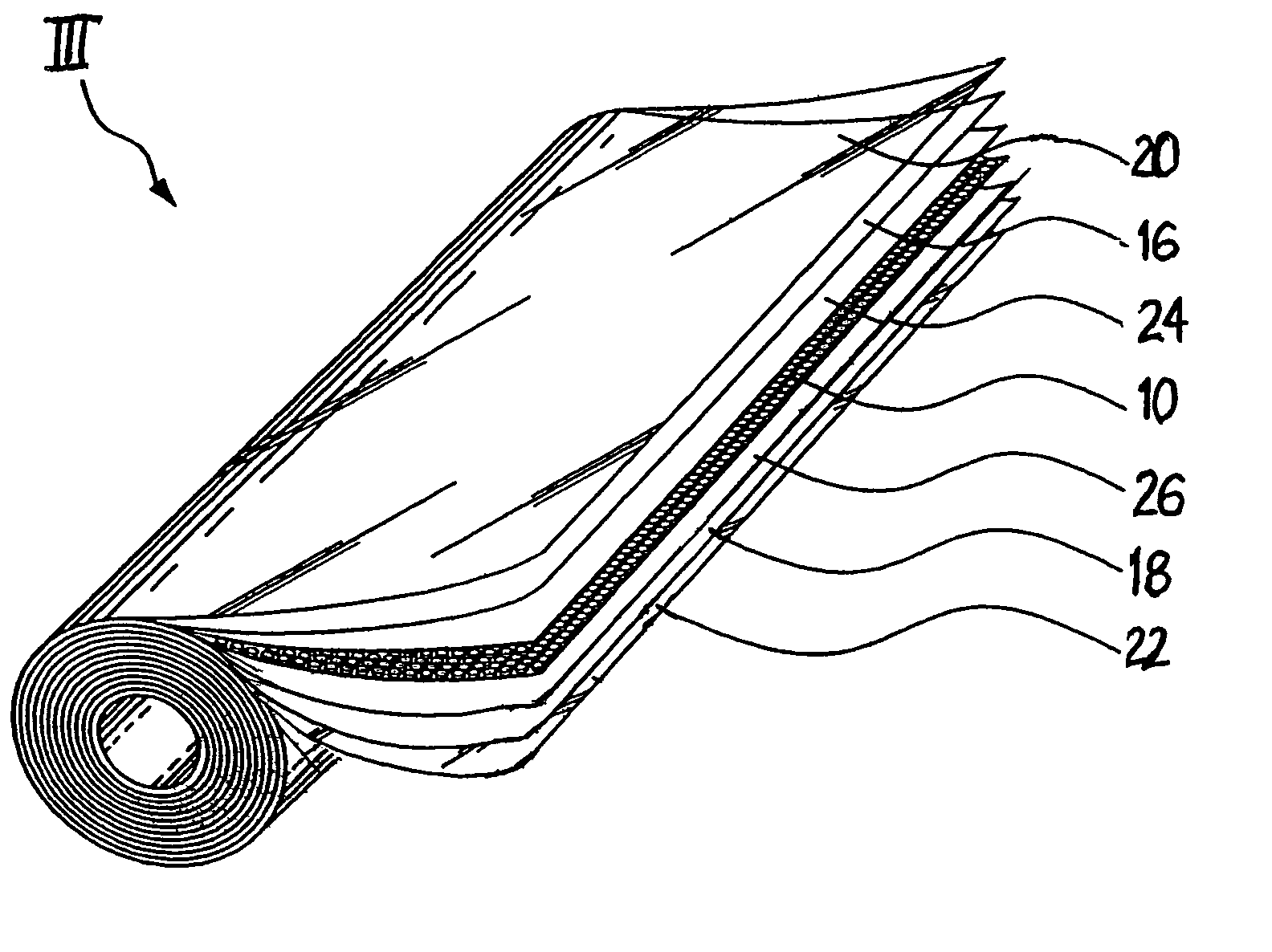
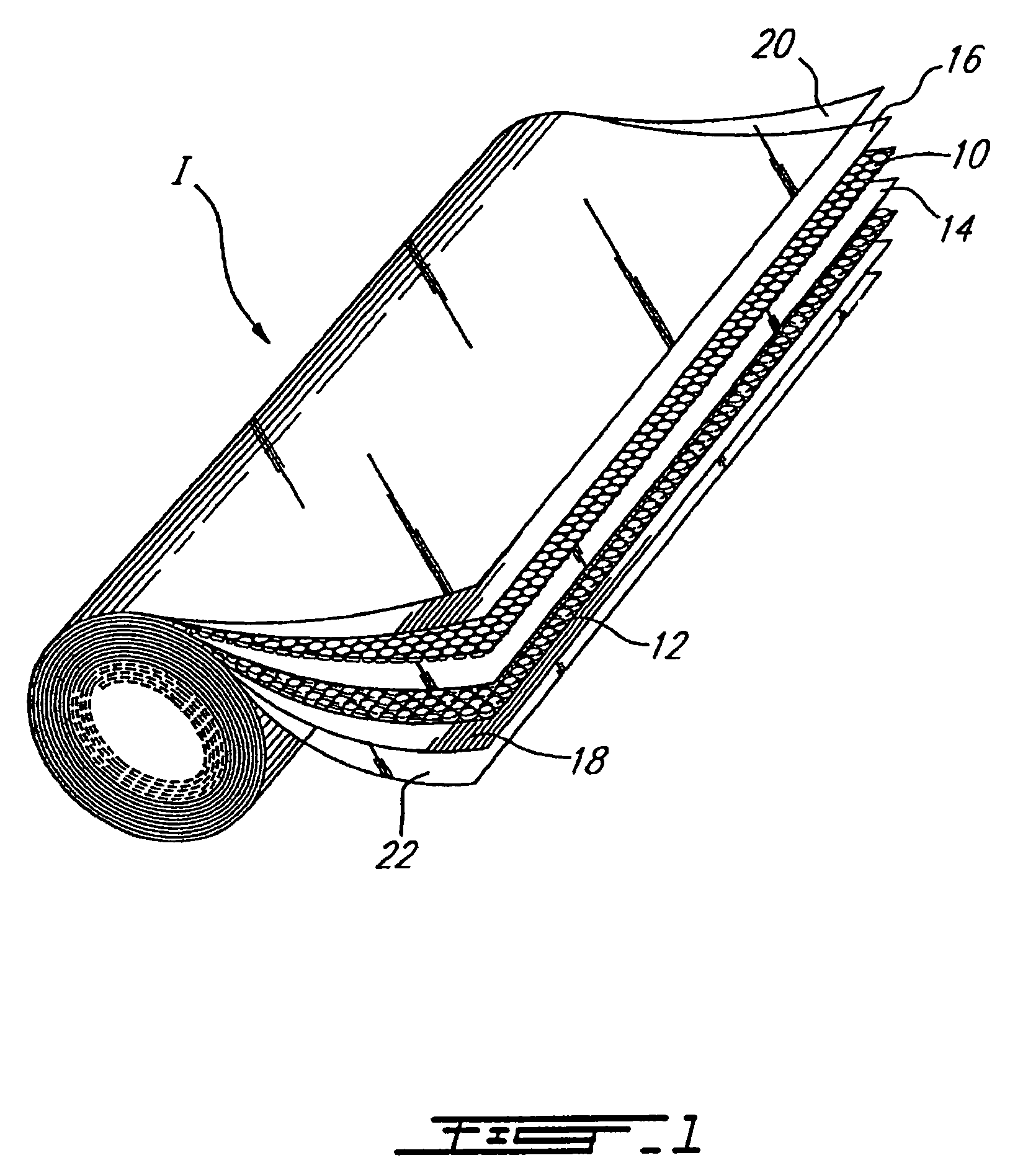
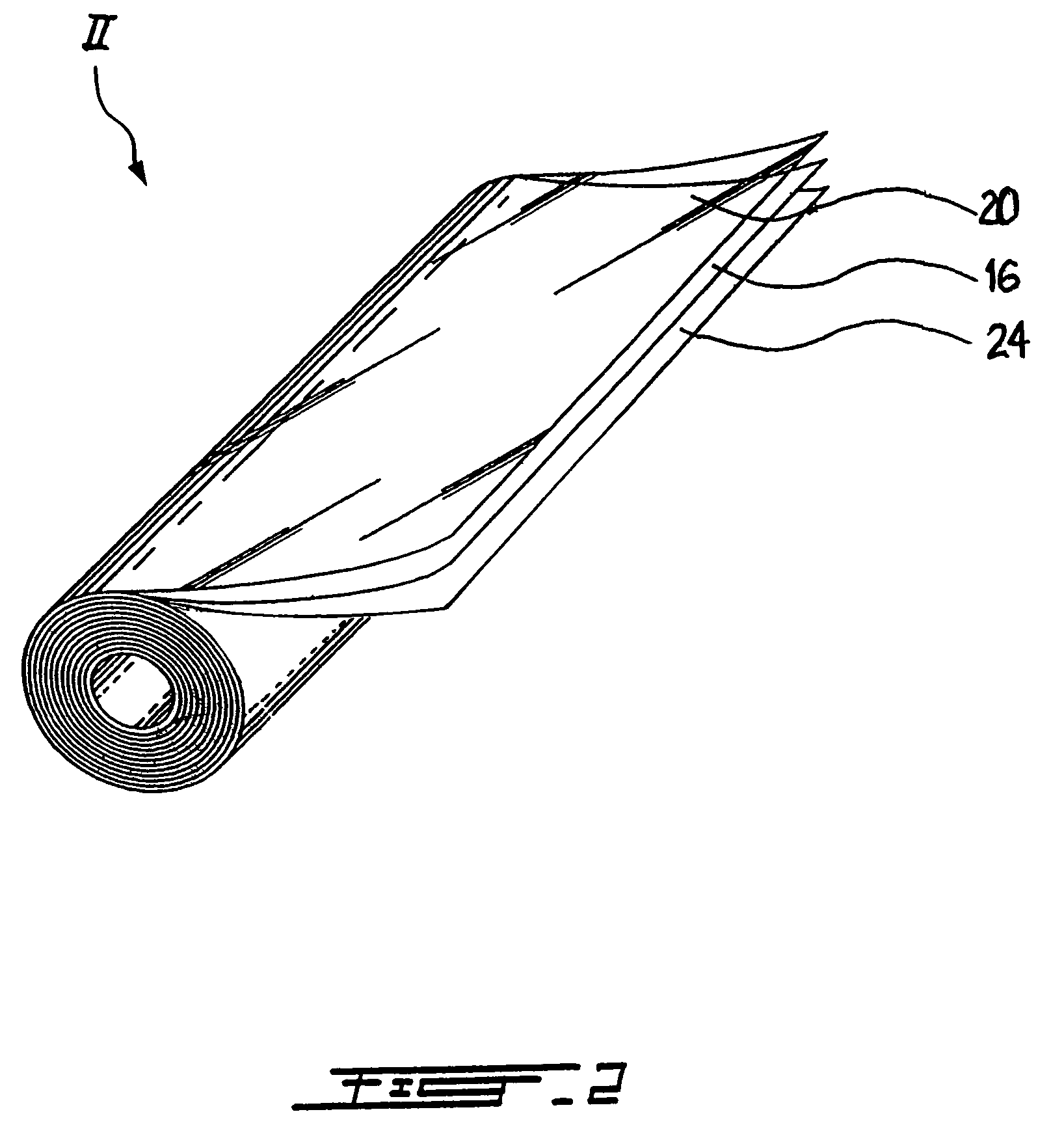
[0047]In accordance with the present invention, FIG. 1 illustrates a roll of flexible insulation I comprising a series of layers which include first and second layers 10 and 12 made of multicellular plastic film (i.e. closed cell air bubbles or bubble-pack) and laminated on both sides of a white 1 mil thick polyethylene film 14; a pair of aluminum foil layers 16 and 18 laminated on the outer surfaces of the bubble-pack layers 10 and 12, and 1 mil thick clear polyester layers 20 and 22 coated on the outer surfaces of the aluminum layers 16 and 18, respectively. The aluminum layers 16 and 18 are vapor deposited on the polyester layers 22 and 24 and are assembled to the bubble-pack layers 10 and 12 which are, in turn, adhered to the central polyethylene film 14. The outer polyester coatings 20 and 22 protect the aluminum layers 16 and 18 such as to prevent any aluminum from rubbing off the insulation I and also prevent the aluminum layers 16 and 18 from oxidizing. Furthermore, the poly...


PUM

PropertyMeasurementUnit
Temperatureaaaaaaaaaa
Melting pointaaaaaaaaaa
Thicknessaaaaaaaaaa

Abstract

A multi-layer flexible insulation (I) comprises a series of layers which include a pair of closed-cell insulation sheets (10,12) made of multicellular plastic film (i.e. closed cell air bubbles or bubble-pack) and laminated on both sides of a thin white polyethylene film (14), a pair of aluminum foil layers or films (16,18) adhesively mounted on the outer surfaces of the bubble-pack insulation sheets (10,12), and a pair of thin clear polyester layers (20,22) provided on the outer surfaces of the aluminum layers. The aluminum layers (16,18) are vapor deposited on the polyester layers (20,22) and are assembled to the hot bubble-pack insulation sheets (10,12) while the latter are cooled. The bubble-pack sheets (10,12) are then adhered to the central polyethylene film (14) with a hot melt glue. If the polyester (20,22) is highly smooth, the aluminum (16,18) can be deposited thereon in a uniform state thereby providing a high reflectivity, low emissivity, laminate. The outer polyester coatings (20,22) also protect the aluminum layers (16,18) such as to prevent any aluminum from rubbing off the insulation (I) and also prevent the aluminum layers (16,18) from oxidizing. Furthermore, the polyester coatings (20,22) provide an hygiene barrier for the insulation (I).

Description

CROSS-REFERENCE[0001]This Application is a Continuation-in-Part of U.S. patent application Ser. No. 09 / 881,720, filed on Jun. 18, 2001 (issued on Oct. 14, 2003 as U.S. Pat. No. 6,632,516), which itself is a Continuation of U.S. patent application Ser. No. 09 / 262,060 filed on Mar. 4, 1999, (issued on Jun. 19, 2001 as U.S. Pat. No. 6,248,433), which itself is a Continuation of PCT / CA97 / 00625 filed on Sep. 3, 1997 designating the United States and claiming priority on U.S. patent application Ser. No. 08 / 706,288 filed on Sep. 4, 1996, abandoned.TECHNICAL FIELD[0002]The present invention relates to thermally insulative materials and, more particularly, to an improved sheet insulation of the reflective bubble type for use, for instance, in arenas, etc.BACKGROUND ART[0003]There are three modes of heat transfer: conduction, convection and radiation (infrared). Of the three, radiation is the primary mode; conduction and convection are secondary and come into play only as matter interrupts or...

Claims


Application Information

Patent Timeline
IPC IPC(8): B32B15/08
CPCB32B15/08B32B27/32B32B27/36B32B3/28F16L59/026F16L59/029F16L59/07F16L59/08B32B27/08B32B2553/026B32B2255/10B32B2255/205B32B2307/102B32B2307/304B32B2307/402B32B2307/416B32B2307/70B32B2439/70Y10T428/31678Y10T428/31786Y10T428/31855Y10T428/31681Y10T428/249953
Inventor AANESTAD, RANGVALD
Owner KRONA INDS
Why Eureka
Try Eureka