Transmission tower devices for reducing longitudinal shock loads

a technology of transceiving towers and shock loads, which is applied in the direction of devices for damping mechanical oscillations, maintaining the distance between parallel conductors, electric cable installations, etc., can solve the problems of increasing the dynamic increasing the and continuing the progressive collapse of large numbers of structures. , to achieve the effect of reducing the peak impact load of the tower

Inactive Publication Date: 2006-06-06
PEABODY ALAN B
View PDF13 Cites 38 Cited by
  • Summary
  • Abstract
  • Description
  • Claims
  • Application Information

AI Technical Summary

Benefits of technology

[0018]Advantageously, the post spring-damper and the rotating crossarm spring-damper are effective in reducing the peak impact loads on towers and thus the potential for lines to cascade. The spring-dampers of the present invention allow for the manufacture of consistent products having consistent results. This is advantageous when compared to devices that use deformable components as the consistency of such components is difficult to ensure. In addition, the operation of the spring-dampers of the present invention is independent of span weight

Problems solved by technology

In the nearly 100 years since those first lines were built, the progressive collapse of large numbers of structures has been a continuing problem.
Cascades can be devastating in their extent.
While not all structural failures result in cascades, longitudinal cascades begin with a failure in the structural system that maintains tension in the overhead wires.
These failures are represented most simply by a broken wire.
Broken wires cause dynamic loads on the towers much higher than the intact wire tensions.
Tension failures have been caused by ice overloads, aircraft strikes and damage due to gunshots, aeolian vibration, galloping and electrical arcing during short circuits.
Suspension insulator assemblies on tangent

Method used


Image

  • Transmission tower devices for reducing longitudinal shock loads
  • Transmission tower devices for reducing longitudinal shock loads
  • Transmission tower devices for reducing longitudinal shock loads

Examples


Embodiment Construction

[0067]In the following description, numerous specific details are set forth to provide a thorough understanding of the invention. However, it is understood that the invention may be practiced without these specific details. In other instances, well-known structures and techniques have not been described or shown in detail in order not to obscure the invention.

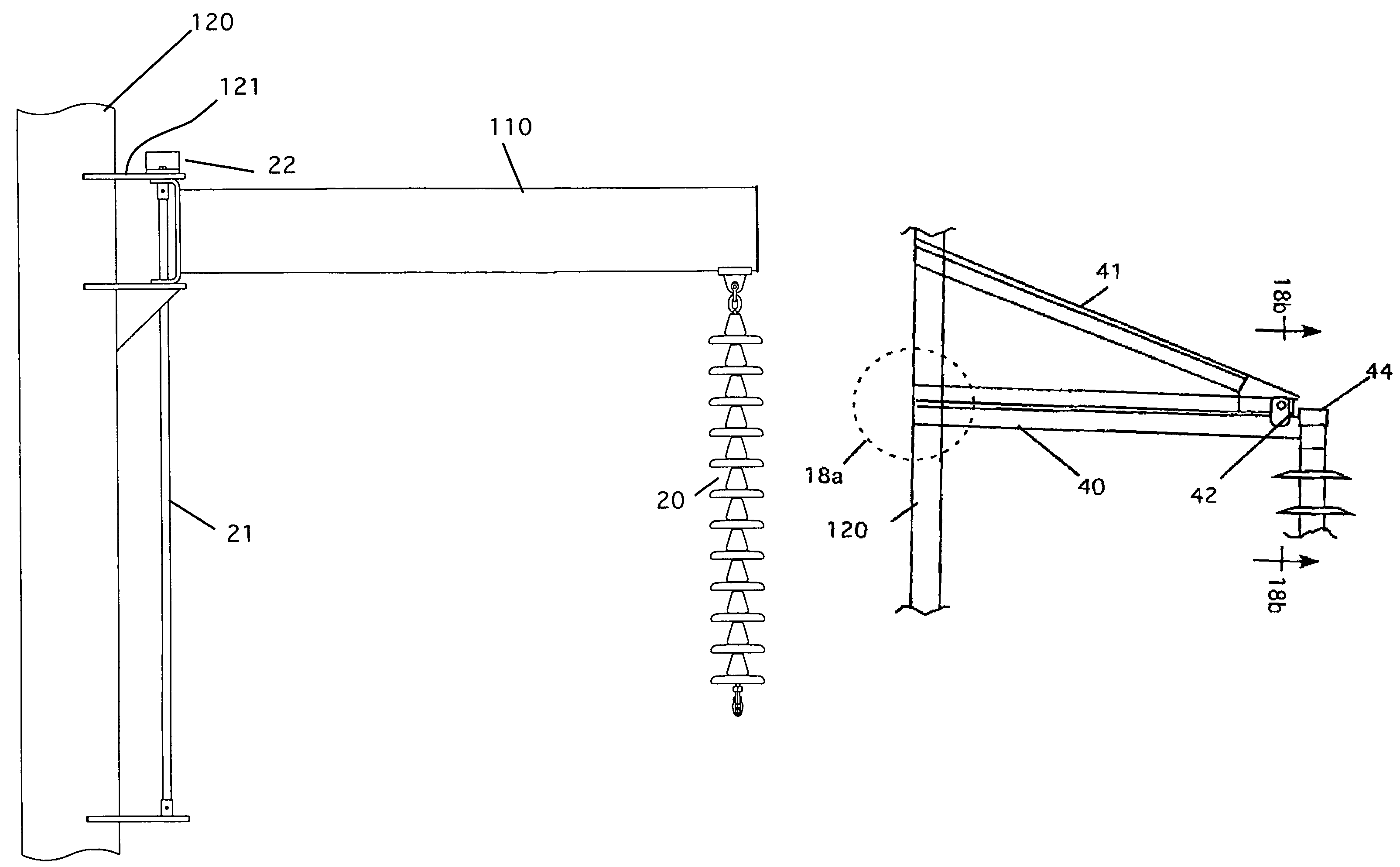
[0068]The present invention provides means for reducing the peak loads on transmission towers due to broken wires and other disturbances to the wire tensioning system.

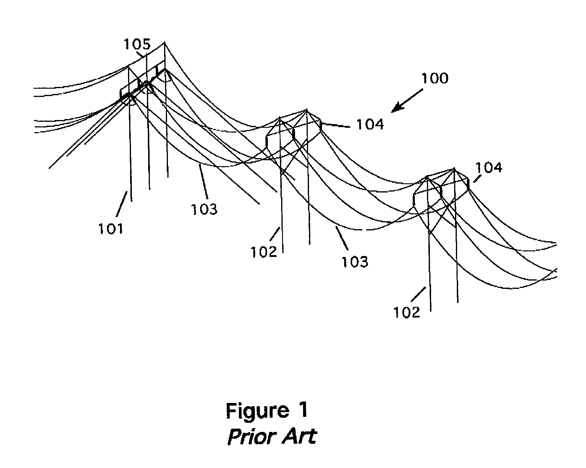
[0069]FIG. 1 is a schematic perspective view illustrating a typical section of H-frame transmission tower line 100 as prior art. The line 100 is made up of a deadend tower 101 and H-frame tangent structures 102. Conductors 103 are suspended by string insulators 104. At the top of the structures is a shield or static wire 105.

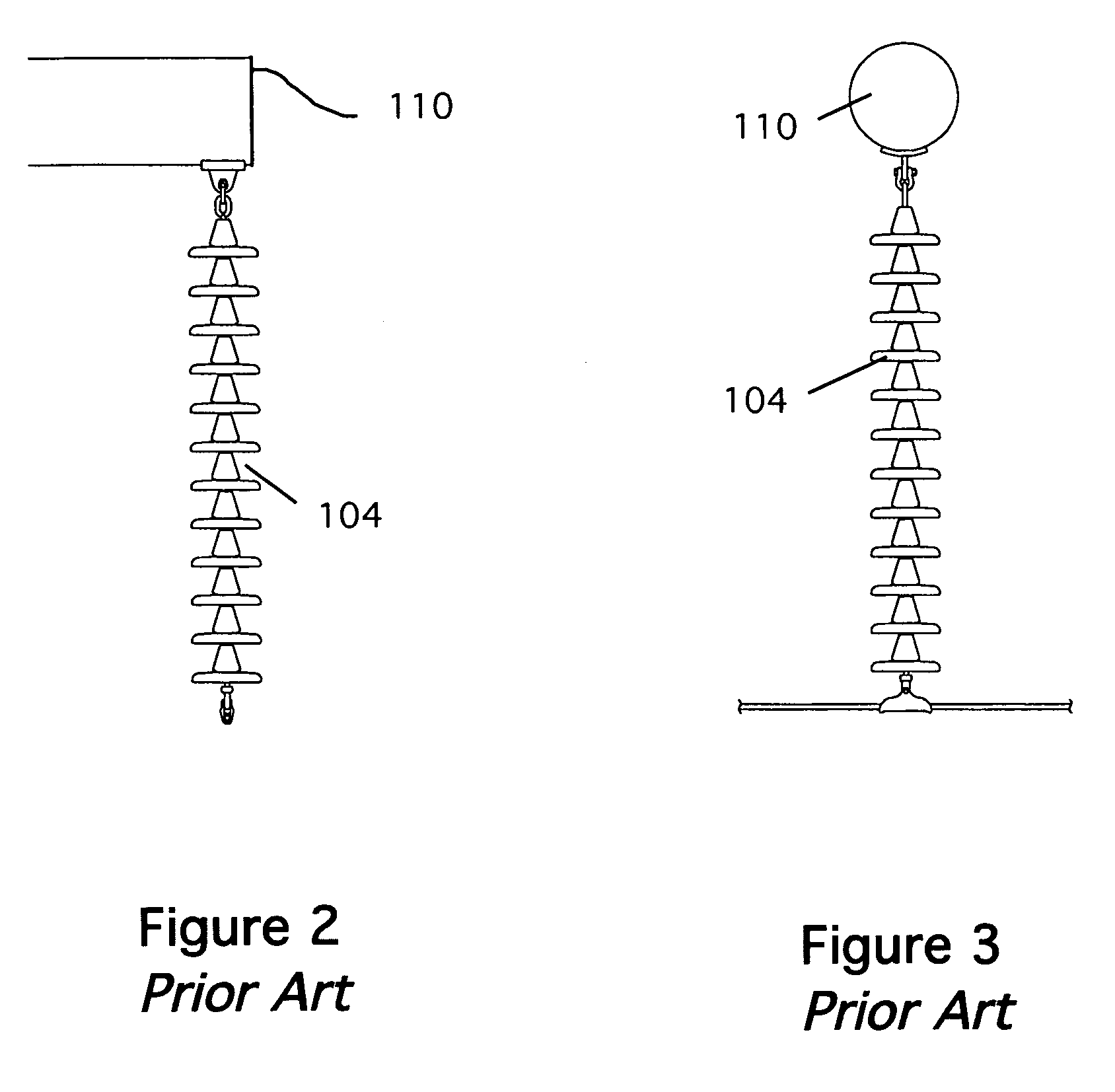
[0070]FIGS. 2 and 3 are front and side views, respectively, illustrating a typical 230 kV porcelain suspension (“I-String”) insulator assembl...


PUM


Abstract

A device for reducing a shock load having a longitudinal direction along a power line coupled through an insulator to a crossarm of a transmission tower, comprising: a rotary damper coupled between the insulator and the crossarm for rotating by the insulator in the longitudinal direction in response to the shock load, the damper having an axle to which the insulator is rotatably coupled; and, a torsion bar coupled at a first end to the axle and at a second end to the crossarm for resisting rotation of the insulator, whereby at least a portion of the shock load is absorbed.

Description

CROSS REFERENCE TO RELATED APPLICATIONS[0001]This application claims the benefit of Provisional Application No. 60 / 568,698 filed May 7, 2004STATEMENT REGARDING FEDERALLY SPONSORED RESEARCH AND DEVELOPMENT[0002]Not ApplicableBACKGROUND OF THE INVENTION[0003]1. Field of the Invention[0004]This invention relates transmission tower devices for reducing longitudinal shock loads and particularly to transmission tower devices for reducing longitudinal shock loads using dampers.[0005]2. Description of the Prior Art[0006]Early in the 20th Century, the design and construction of high-voltage overhead electric 10 power lines began. In the nearly 100 years since those first lines were built, the progressive collapse of large numbers of structures has been a continuing problem. These large-scale progressive collapses are known today as “cascades”.[0007]Cascades are typically defined as the progressive collapse of more than two (or three) structures in either direction from an initial failure. In...

Claims


Application Information

Patent Timeline
IPC IPC(8): H02G7/20
CPCH02G7/14
Inventor PEABODY, ALAN B
Owner PEABODY ALAN B
Why Eureka
Try Eureka