Operation of an electrical machine

a polyphase, electrical machine technology, applied in the direction of electronic commutators, single motor speed/torque control, synchronous motor starters, etc., can solve the problems of increasing the overall assembly cost, adding extra electrical connections to the machine, and potential sources of unreliability, so as to reduce the duty of at least one phase

Active Publication Date: 2006-06-06
NIDEC SR DRIVES
View PDF24 Cites 26 Cited by
  • Summary
  • Abstract
  • Description
  • Claims
  • Application Information

AI Technical Summary

Benefits of technology

[0018]In one form, an embodiment of the invention provides a method of operating a polyphase electrical machine, the method comprising: reducing the duty of at least one phase for a given output demand; and increasing the duty of the other phase(s) to compensate for the reduction in the duty of the at least one phase for the given output demand, in which the variation in the duty of the phases allows, for example, advantageous rotor position detection at low loads.
[0019]The duty of the phase is its contribution to the overall output of the machine made up of the plurality of phase outputs. Under ideal normal running conditions, the duty of each phase is equal. This embodiment of the invention varies the duty in at least one of the phases and adjusts the output in the others to compensate. This facilitates robust and cost-effective rotor position detection over a wider range of system loads than previously thought possible.
[0023]According to one particular form, the method includes sensing a parameter of the machine; determining when the parameter passes a predetermined threshold; and reducing the duty of the at least one phase in response.

Problems solved by technology

However, the rotor position transducer increases the overall cost of assembly, adds extra electrical connections to the machine and is, therefore, a potential source of unreliability.
While this is not a problem when the machine is on full load or a significant fraction of it, if the machine is called on to operate at a particular speed at no-load or a very small output, the flux or current (for example) is often so small that the position detection algorithms are at best error prone and often completely fail, and the control system consequently loses control of the machine.
In many applications this is unacceptable.

Method used


Image

  • Operation of an electrical machine
  • Operation of an electrical machine
  • Operation of an electrical machine

Examples


Embodiment Construction

[0042]The illustrative embodiment to be described uses a 3-phase switched reluctance drive in the motoring mode, but any phase number greater than one could be used, with the drive in either motoring or generating mode.

[0043]When a balanced, polyphase electrical machine is operating in steady state, all of the phases contribute equally to the output of the machine and the input phase quantities are equal. For example, if the machine is in the motoring mode then the output is mechanical power and the input is balanced phase currents. If the machine is operating in the generating mode, the output is electrical power in the form of balanced phase currents and the input is mechanical power to the rotor. In these cases, the machine is said to share the duty of providing the demanded output equally among the phases.

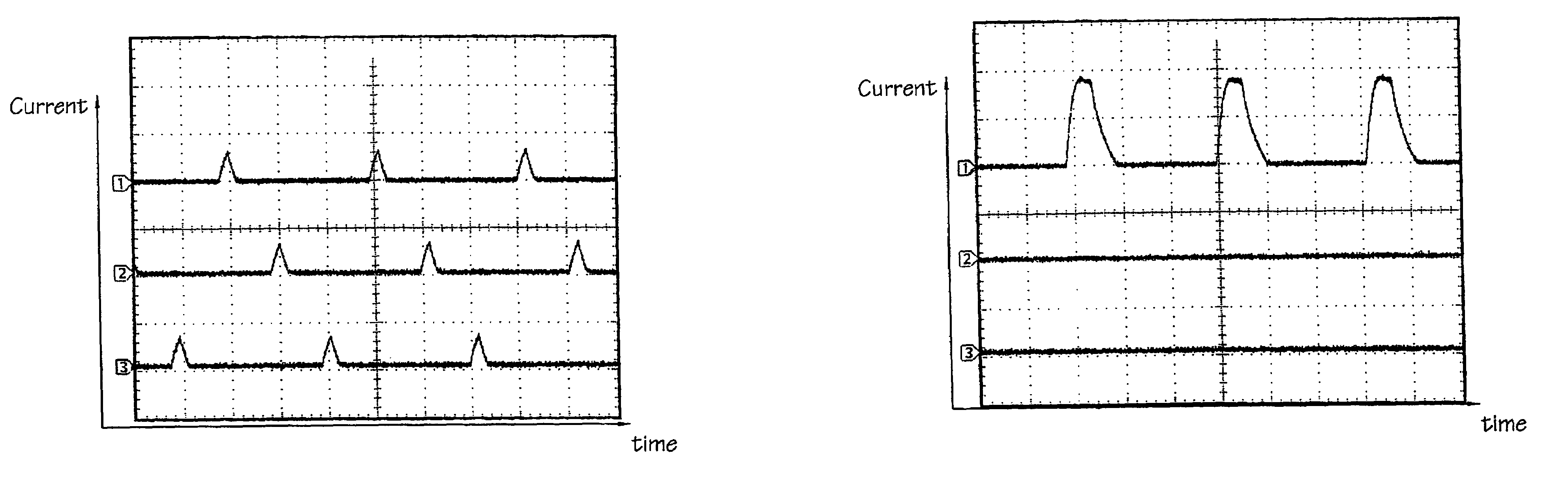
[0044]FIG. 6 shows the measured phase current waveforms of an exemplary 3-phase switched reluctance machine operating near its full load of 22 kW at 4000 rev / min. As would be e...


PUM


Abstract

An electrical machine is controlled without using a physical rotor position detector. When the demanded torque output is low, a control method causes the machine to operate on fewer than all the phases, thus increasing the phase current and improving the resolution of the position detection algorithm. The method can include sampling the phase current of the machine, determining whether the phase current is above a predetermined threshold, reducing the number of active phases, and then deriving the value of rotor position from the increased phase current in the remaining phases.

Description

CROSS-REFERENCE TO RELATED APPLICATION[0001]The subject matter of this application is related to the subject matter of British Patent Application No. GB 0325955.3, filed Nov. 6, 2003, priority to which is claimed under 35 U.S.C. § 119 and which is incorporated herein by reference.BACKGROUND OF THE INVENTION[0002]1. Field of the Invention[0003]This invention relates to the operation of a polyphase electrical machine, particularly, but not exclusively, a polyphase switched reluctance machine.[0004]2. Description of Related Art[0005]The characteristics and operation of switched reluctance systems are well known in the art and are described in, for example, “The characteristics, design and application of switched reluctance motors and drives” by Stephenson and Blake, PCIM'93, Nüurnberg, 21–24 Jun. 1993, incorporated herein by reference. FIG. 1 shows a typical switched reluctance drive in schematic form, where the switched reluctance motor 12 drives a load 19. The input DC power supply 1...

Claims


Application Information

Patent Timeline
Patent Type & Authority Patents(United States)
IPC IPC(8): H02P25/08H02P6/18
CPCH02P6/18H02P25/083H02P2203/09H02P2203/01H02P25/089
Inventor NORMAN, ROSEMARY ANNE
Owner NIDEC SR DRIVES
Why Eureka
Try Eureka