Multiple camera control system

a control system and camera technology, applied in the direction of camera focusing arrangement, image enhancement, printers, etc., can solve the problem of becoming impractical to provide access to a computer mouse or trackball

Inactive Publication Date: 2006-06-06
QUALCOMM INC
View PDF52 Cites 714 Cited by
  • Summary
  • Abstract
  • Description
  • Claims
  • Application Information

AI Technical Summary

Benefits of technology

[0009]Processing the first image data set and the second image data set to generate the background data set may include generating a first set of one or more background data sets associated with the first image data set, and generating a second set of one or more background data sets associated with the second image data set.
[0010]Generating the first set of one or more background data sets may include generating a first background set representing a maximum value of data within the first image data set representative of the background, and generating the second set of one or more background data sets includes generating a second background set representing a maximum value of data within the second image data set representative of the background. Generating further may include, for the first and second background sets representing

Problems solved by technology

However, for someone who is unfamiliar with operating a computer mouse, selecting GUI functions may present a challenge that prevents them from interfacing with the computer system.
There also exist situations where it becomes im

Method used


Image

  • Multiple camera control system
  • Multiple camera control system
  • Multiple camera control system

Examples


Embodiment Construction

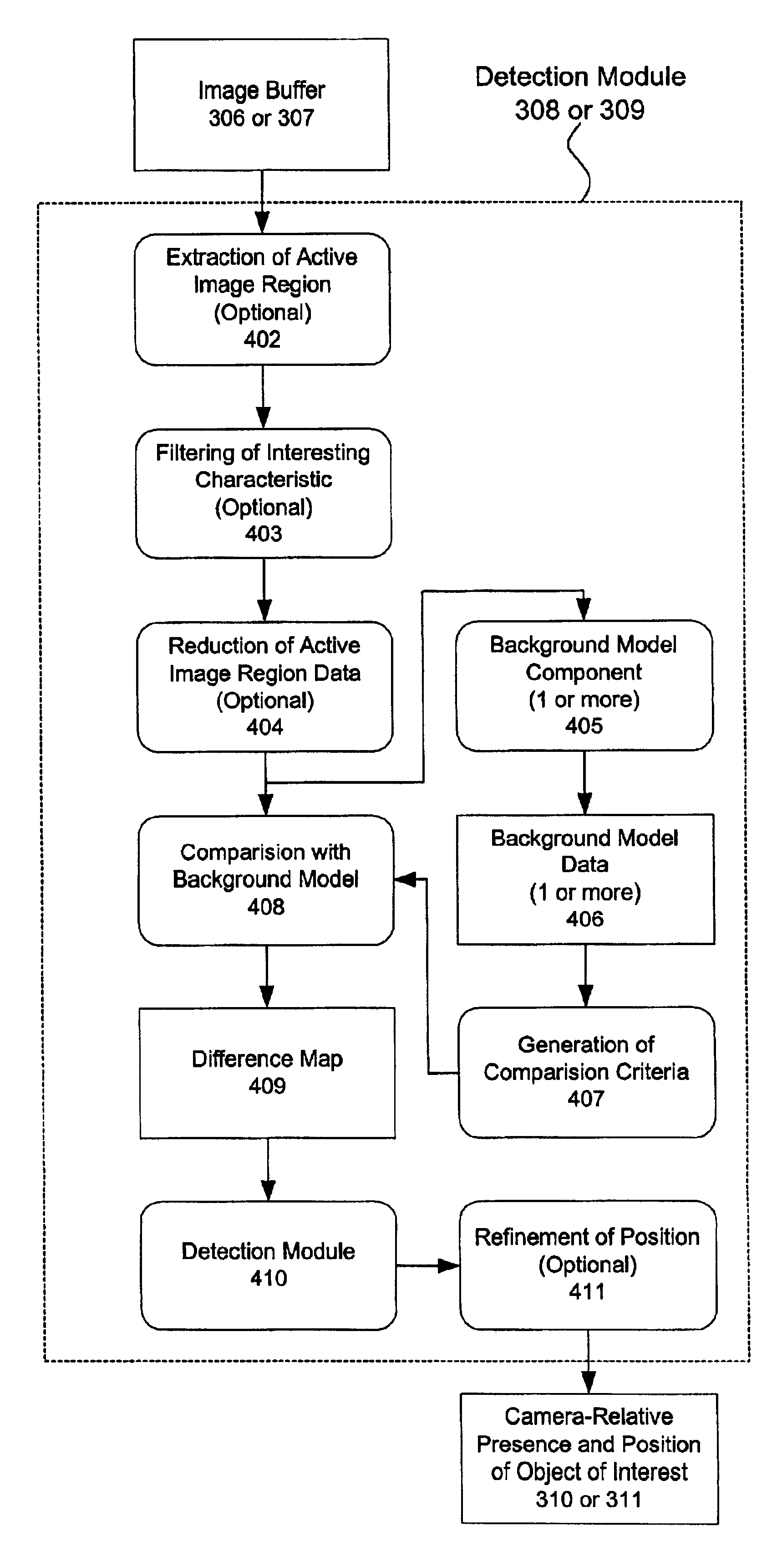
[0063]FIG. 1 shows a multicamera motion tracking and control system 100 interfaced with an image viewing system. In this implementation two cameras 101 and 102 scan a region of interest 103. A controlled or known background 104 surrounds the region of interest 103. An object of interest 105 is tracked by the system when it enters the region of interest 103. The object of interest 105 may be any generic object inserted into the region of interest 103, and is typically a hand or finger of a system user. The object of interest 105 also may be a selection device such as a pointer.

[0064]The series of video images acquired from the cameras 101 and 102 are conveyed to a computing device or image processor 106. In this implementation, the computing device is a general-purpose computer that runs additional software that provides feedback to the user on a video display 107.

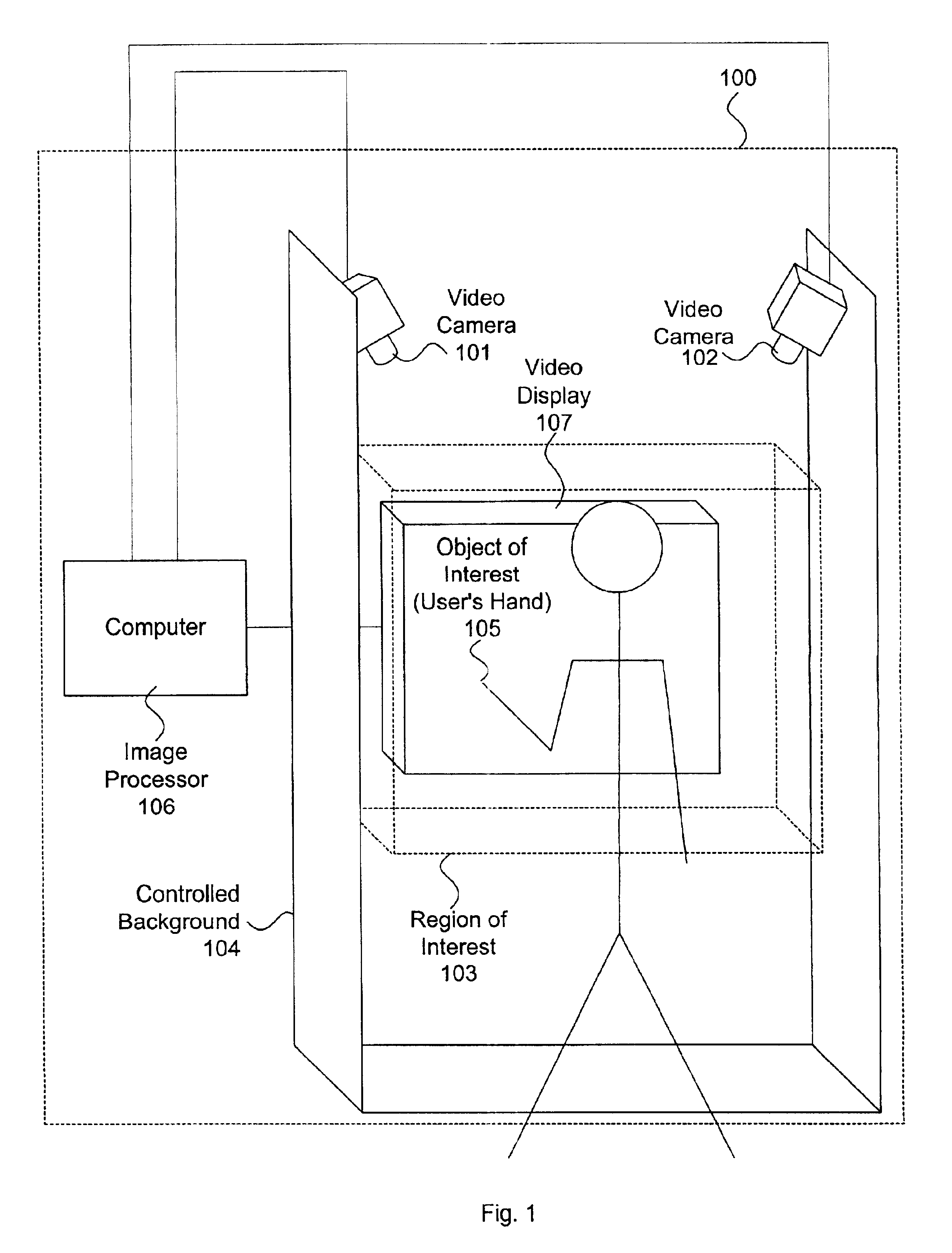
[0065]FIG. 2A illustrates a typical implementation of the multicamera control system 100. The two cameras 101 and 102 are...


PUM


Abstract

A multiple camera tracking system for interfacing with an application program running on a computer is provided. The tracking system includes two or more video cameras arranged to provide different viewpoints of a region of interest, and are operable to produce a series of video images. A processor is operable to receive the series of video images and detect objects appearing in the region of interest. The processor executes a process to generate a background data set from the video images, generate an image data set for each received video image, compare each image data set to the background data set to produce a difference map for each image data set, detect a relative position of an object of interest within each difference map, and produce an absolute position of the object of interest from the relative positions of the object of interest and map the absolute position to a position indicator associated with the application program.

Description

CROSS REFERENCE TO RELATED APPLICATION[0001]This application claims priority from U.S. Provisional Application No. 60 / 237,187, filed Oct. 3, 2000, and titled DUAL CAMERA CONTROL SYSTEM, which is incorporated by reference.TECHNICAL FIELD[0002]This invention relates to an object tracking system, and more particularly to a video camera based object tracking and interface control system.BACKGROUND[0003]A variety of operating systems are currently available for interacting with and controlling a computer system. Many of these operating systems use standardized interface functions based on commonly accepted graphical user interface (GUI) functions and control techniques. As a result, different computer platforms and user applications can be easily controlled by a user who is relatively unfamiliar with the platform and / or application, as the functions and control techniques are generally common from one GUI to another.[0004]One commonly accepted control technique is the use of a mouse or t...

Claims


Application Information

Patent Timeline
IPC IPC(8): G06K9/00G06T5/00G06T5/50G06T7/00G06T7/20G06T7/60
CPCG06K9/00375G06T5/50G06T7/0075G06T7/0081G06T7/2053G06T7/0097G06T2207/20132G06T2207/10016G06T2207/10021G06T7/593G06T7/11G06T7/174G06T7/254G06V40/107
Inventor HILDRETH, EVANMACDOUGALL, FRANCIS
Owner QUALCOMM INC
Why Eureka
Try Eureka