Optical device having a waveguide lens with multimode interference

a waveguide lens and optical device technology, applied in the field of optical communication equipment, can solve the problems of difficult task of accurately representing the desired index of refraction distribution, inability to incorporate waveguide lenses similar to lenses b>110/b> into waveguide devices designated for large-scale production,

Active Publication Date: 2006-06-06
ALCATEL-LUCENT USA INC +1
View PDF6 Cites 18 Cited by
  • Summary
  • Abstract
  • Description
  • Claims
  • Application Information

AI Technical Summary

Benefits of technology

[0008]Problems in the prior art are addressed, in accordance with the principles of the present invention, by a waveguide lens with multimode interference. In one embodiment, a waveguide lens of the invention has a pair of planar waveguides, e.g., a single-mode waveguide connected to a multimode waveguide. The widths of the two waveguides and the length of the multimode waveguide are selected such that particular mode coupling between the waveguides and multimode interference (MMI) effects in the multimode waveguide cause the latter to output a converging beam of light similar to that produced by a conventional waveguide lens. Advantageously, waveguide lenses of the invention may be used to implement low-loss, low-crosstalk waveguide crossings and / or compact waveguide turns. In addition, waveguide lenses of the invention can be readily and cost-effectively incorporated into waveguide devices designated for large-scale production.

Problems solved by technology

One problem with lens 110 is that the diffusion film used for its fabrication has an inherently small thickness, which turns the task of creating a thickness profile accurately representing the desired index of refraction distribution into a relatively difficult proposition.
As a result, incorporation of waveguide lenses similar to lens 110 into waveguide devices designated for large-scale production may not be practical.

Method used


Image

  • Optical device having a waveguide lens with multimode interference
  • Optical device having a waveguide lens with multimode interference
  • Optical device having a waveguide lens with multimode interference

Examples


Embodiment Construction

[0024]Reference herein to “one embodiment” or “an embodiment” means that a particular feature, structure, or characteristic described in connection with the embodiment can be included in at least one embodiment of the invention. The appearances of the phrase “in one embodiment” in various places in the specification are not necessarily all referring to the same embodiment, nor are separate or alternative embodiments mutually exclusive of other embodiments.

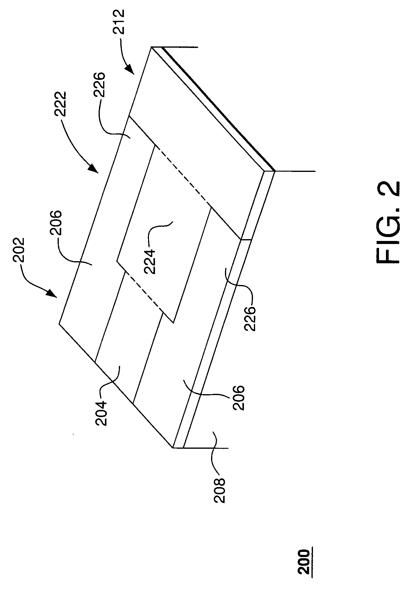
[0025]FIG. 2 shows a three-dimensional perspective view of an optical device 200 according to one embodiment of the present invention. Device 200 is analogous to device 100 of FIG. 1 and includes a first planar waveguide 202 coupled to a second planar waveguide 222, the latter coupled to a slab region 212. Each waveguide has a core region and two adjacent cladding regions formed on a substrate 208. In particular, waveguide 202 has core region 204 and cladding regions 206, and waveguide 222 has core region 224 and cladding regions 2...


PUM


Abstract

In one embodiment, a waveguide lens of the invention has a pair of planar waveguides, e.g., a single-mode waveguide connected to a multimode waveguide. The widths of the two waveguides and the length of the multimode waveguide are selected such that particular mode coupling between the waveguides and multimode interference (MMI) effects in the multimode waveguide cause the latter to output a converging beam of light similar to that produced by a conventional waveguide lens. Advantageously, waveguide lenses of the invention may be used to implement low-loss, low-crosstalk waveguide crossings and / or compact waveguide turns. In addition, waveguide lenses of the invention can be readily and cost-effectively incorporated into waveguide devices designated for large-scale production.

Description

BACKGROUND OF THE INVENTION[0001]1. Field of the Invention[0002]The present invention relates to optical communication equipment and, more specifically, to optical waveguide devices.[0003]2. Description of the Related Art[0004]FIG. 1 shows a three-dimensional perspective view of an optical device 100 having a prior art waveguide lens 110. More specifically, device 100 includes a planar waveguide 102 having a core region 104 and two cladding regions 106 formed on a substrate 108. The index of refraction of core region 104 is higher than those of cladding regions 106 and substrate 108, which provides both lateral and transverse confinement of light in the core region. Waveguide 102 is coupled via lens 110 to a slab region 112, which has the same index of refraction as core region 104. Similar to waveguide 102, slab region 112 provides the transverse confinement of light due to the index of refraction contrast between that region and substrate 108. However, due to the absence of the co...

Claims


Application Information

Patent Timeline
Patent Type & Authority Patents(United States)
IPC IPC(8): G02B6/32G02B6/14G02B6/122G02B6/125G02B6/28
CPCG02B6/122G02B6/125G02B6/2813
Inventor STUART, HOWARD R.
Owner ALCATEL-LUCENT USA INC
Why Eureka
Try Eureka