Variable geometry turbocharger

a variable geometry, turbocharger technology, applied in the direction of reaction engines, machines/engines, liquid fuel engines, etc., can solve the problems of reducing the service life of the turbocharger, reducing the cost associated with using solid vanes, and difficult to move the vane within the turbocharger, etc., to increase the operating efficiency of the turbocharger

Active Publication Date: 2006-06-13
GARRETT TRANSPORATION I INC
View PDF15 Cites 22 Cited by
  • Summary
  • Abstract
  • Description
  • Claims
  • Application Information

AI Technical Summary

Benefits of technology

[0012]A key feature of vanes of this invention is that at least one of the first and second axial surfaces comprises a composite construction of a solid section and a cored-out section. In an example embodiment, the solid section extends a distance from the leading edge towards the trailing edge, and the cored-out section extends a distance from the trailing edge towards the leading edge. The solid and cored-out sections are positioned and configured to minimize or eliminate the undesired passage of gas along the vane axial surface, thereby operating to increase turbocharger operating efficiency.

Problems solved by technology

While such conventional solid vanes 10 are useful in variable geometry turbochargers, the solid design of the vanes is known to make vane mobility within the turbocharger more difficult, and is known to impose related friction effects on the vanes and related vane movement mechanisms within the turbocharger that can reduce operational service life of the turbocharger.
Additionally, the cost associated with using solid vanes is relatively expensive.
However, the cored-out structure of such vanes may operate to permit undesired air flow effects to occur within the turbocharger.
For example, air being directed to the vane leading edge and airfoil surfaces, rather then being directed along the airfoil surfaces, can leak between the vane axial surfaces and adjacent turbocharger surfaces due to the reduced resistance to airflow that is provided by the core-out configuration.
Such vane leakage within the turbocharger is not desired as it adversely impacts turbocharger operating efficiency.

Method used


Image

  • Variable geometry turbocharger
  • Variable geometry turbocharger
  • Variable geometry turbocharger

Examples


Embodiment Construction

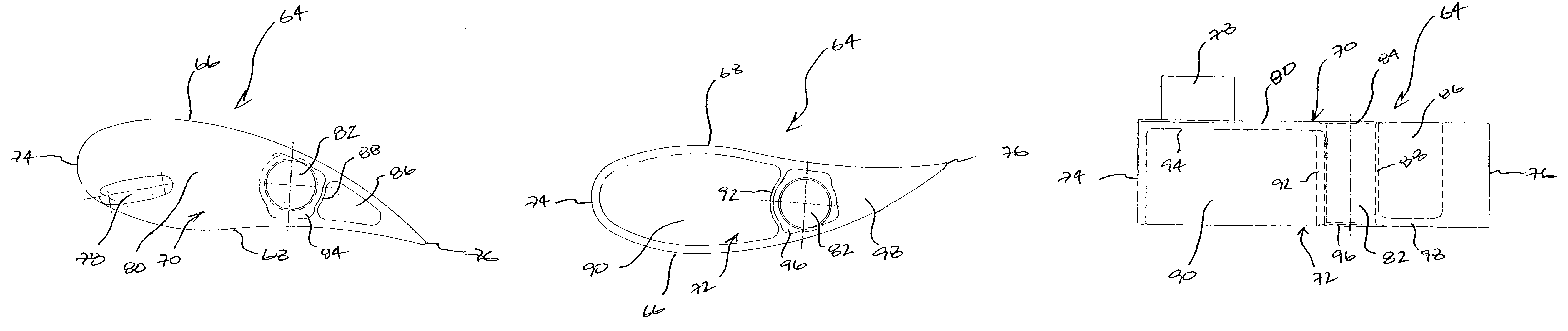
[0019]Vanes of this invention, constructed for use in a variable geometry turbocharger, are configured having axial surfaces that are each characterized by strategically positioned cored-out and solid surfaces. More specifically, vanes of this invention have a first axial surface that is solid along a major surface area, and a second axial surface that is cored-out along a major surface area. Each of the first and second axial surfaces also include respective cored-out and solid sections that occupies a minor surface area of the respective axial surface. Vanes of this invention are so configured to minimize or eliminate possible leak paths across the vane axial surfaces during turbocharger operation.

[0020]Vanes of this invention are disposed within a variable geometry or variable nozzle turbocharger. Such variable geometry turbochargers generally comprise a center housing having a turbine housing attached at one end, and a compressor housing attached at an opposite end. A shaft is r...


PUM


Abstract

A variable geometry turbocharger includes vanes disposed therein having an inner airfoil surface oriented adjacent a turbine wheel, and an outer airfoil surface oriented opposite and parallel to the inner airfoil surface. The vane includes first and second axial surfaces that are each positioned perpendicular to and interposed between the inner and outer airfoil surfaces. A vane leading edge is positioned along a first inner and outer airfoil surface junction, and a trailing edge is positioned along a second inner and outer airfoil surface junction. One or more of the first and second axial surfaces have a composite construction comprising a solid section that extends a distance from the leading edge towards the trailing edge, and a cored-out section that extends a distance from the trailing edge towards the leading edge.

Description

FIELD OF THE INVENTION[0001]This invention relates generally to the field of variable geometry turbochargers and, more particularly, to aerodynamic vanes that are movably disposed therein that are lightweight, when compared to conventional solid vanes, and that display low gas leakage, when compared to known non-solid vanes, thereby providing improved vane operation and extended vane / turbocharger service life.BACKGROUND OF THE INVENTION[0002]Turbochargers for gasoline and diesel internal combustion engines are devices known in the art that are used for pressurizing or boosting the intake air stream, routed to a combustion chamber of the engine, by using the heat and volumetric flow of exhaust gas exiting the engine. Specifically, the exhaust gas exiting the engine is routed into a turbine housing of a turbocharger in a manner that causes an exhaust gas driven turbine to spin within the housing. The exhaust gas-driven turbine is mounted onto one end of a shaft that is common to a rad...

Claims


Application Information

Patent Timeline
Patent Type & Authority Patents(United States)
IPC IPC(8): F02D23/00F01D17/12F01D17/16F01D5/14F01D11/00F02B37/24F02C6/12
CPCF01D17/165F02B37/24F05D2240/12F05D2250/291F05D2220/40F01D5/141F01D11/005F02C6/12F05D2250/411
Inventor ZOLLINGER, BRENT D.SLUPSKI, KEVIN P.RIETHMEIER, DOUGLAS H.
Owner GARRETT TRANSPORATION I INC
Why Eureka
Try Eureka