Endotracheal tube cleaning apparatus and method

a technology of endotracheal tubes and cleaning apparatus, which is applied in the direction of catheters, balloon catheters, respirators, etc., can solve the problems of significant increase in the work of breathing increased morbidity and hospital costs for the incubated patient, and significant prolongation of the incubation period and icu stay of the patient, so as to facilitate the re-introduction and added cleaning of the endotracheal tube, and facilitate the adjustment of the inflated amoun

Inactive Publication Date: 2006-06-13
MOREJON ORLANDO
View PDF30 Cites 47 Cited by
  • Summary
  • Abstract
  • Description
  • Claims
  • Application Information

AI Technical Summary

Benefits of technology

[0017]It is an object of the present invention to provide an endotracheal tube cleaning apparatus which can efficiently and easily be routinely utilized to maintain the flow through passage of an endotracheal tube free from the accumulation of dried tracheobronchial secretions.
[0029]Another object of the present invention is to provide an endotracheal tube cleaning apparatus which is convenient to grasp and manipulate and which provides for easy adjustment of the inflated amount of the resilient material bladder.

Problems solved by technology

Recent studies have determined, however, that the accumulation of dried tracheo-bronchial secretions on the interior wall surface of an operating endotracheal tube effectively decreases the lumen cross section, and thereby significantly increases the work of breathing for the incubated patient.
Moreover, increasing the work of breathing for the patient necessitates that a higher level of support be provided to compensate, and often results in the patient's incubation period and ICU stay being significantly prolonged.
Furthermore, it is also seen that thick secretions on the walls of the endotracheal tube often serve as a nidus for continued infection in the lungs, leading to added morbidity and hospital costs for the incubated patient.
There are, however, several disadvantages to this procedure, such as temporary arrest of ventilatory support and the risk of complete loss of airway control.
For example, re-incubation may be exceedingly difficult in patients with swelling of the soft tissue of the neck, and in patients having cervical spine immobilization, because upon removal of the endotracheal tube, the appropriate internal passages tend to close up and be otherwise difficult to isolate for reintroduction of a new endotracheal tube.
Further, re-incubation of a patient can result in additional trauma to the oral, laryngeal and tracheal tissues.
Unfortunately, although the suction / irrigation catheters generally clear the airway of watery secretions, they are ineffective at clearing the inspissated secretions that have accumulated on the inner wall surface of the endotracheal tube over the course of days.
Such a device, however, does not provide for accurate insertion indication to prevent over-insertion into the endotracheal tube, and completely seals off the endotracheal tube during removal so as to result in a potentially hazardous interruption to ventilation and / or a negative pressure or suction behind the cleansing device.
Furthermore, it is seen from the need to include the bristles, that direct engagement of a gasket type member, such as the balloon, with the interior wall surface of the endotracheal tube, does not provide for the complete and effective removal of secretions, due primarily to the smooth exterior surface of the gasket.
Moreover, the smooth resilient material surface also results in substantial friction between the rubbery gasket and the plastic wall surface, thereby making it quite difficult to smoothly and effectively pull the cleansing device from the endotracheal tube.
Additionally, it is seen that upwardly angled bristle members are susceptible to complete or partial retraction as they encounter obstacles and attempt to scrape clean the interior of the endotracheal tube, and in fact, the bristle members are often quite sharp and may be damaging to the endotracheal tube or to a patient if inadvertently projected beyond the endotracheal tube so that the outwardly projecting bristle members become stuck outside the endotracheal tube.
Also, because of the collapsing configuration of bristles, gaps will naturally exist between adjacent bristles and some areas of the tube are not engaged, and as secretions begin to build up beneath the bristles, their collapse is further restricted.
Further, such a single function device necessitates that additional items be introduced into the tube, generally resulting in additional trauma to the patient, if some suction is necessary.

Method used


Image

  • Endotracheal tube cleaning apparatus and method
  • Endotracheal tube cleaning apparatus and method
  • Endotracheal tube cleaning apparatus and method

Examples


Embodiment Construction

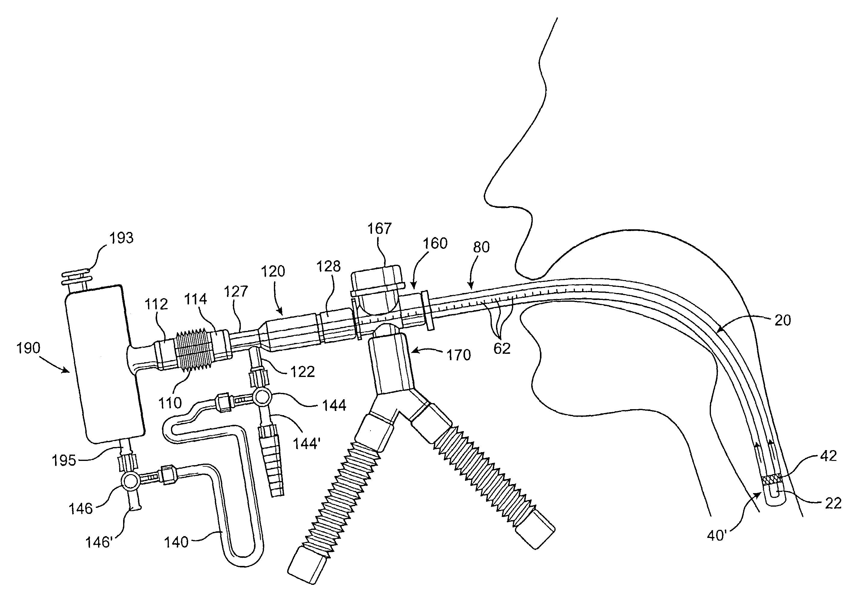
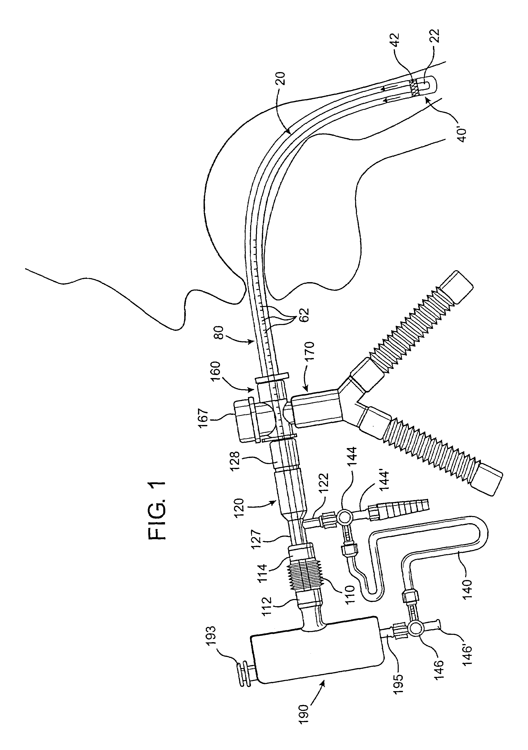
[0043]Shown throughout the Figures, the present invention is directed toward an endotracheal tube cleaning apparatus, generally indicated as 10. In particular, the endotracheal tube cleaning apparatus 10 is constructed for use with an endotracheal tube 80 that is conventionally utilized to enable a patient to breathe, and as such, is generally inserted down the throat of a patient as illustrated in FIG. 1. Such an endotracheal tube 80 is preferably of the type including a flow through passage 82 having an interior wall surface 83 that defines its interior diameter. Generally, however, after prolonged periods of use, the endotracheal tube 80 will exhibit a buildup of secretions 85 that form on the interior wall surface 83 and can thereby obstruct airflow through the flow through passage 82. The endotracheal tube cleaning apparatus 10 of the present invention, among other functions, is structured to facilitate the removal of those secretions 85 in a convenient and effective manner.

[00...


PUM


Abstract

A cleaning apparatus and method to be used with an endotracheal tube and including an elongate tubular member that extends into the endotracheal tube. A cleaning assembly which may include an irregular outer surface is provided at a distal end of the elongate tubular member and is radially expandable to engage the interior wall of the endotracheal tube for cleaning thereof. A ventilator coupling is further provided and is connected to the endotracheal tube, a first inlet port of the ventilator coupling being coupled to a ventilator assembly to supply air to a patient, and a second inlet port of the ventilator coupling being structured to receive the elongate tubular member there through into the endotracheal tube. Also, a bypass coupling assembly is connected between the channel of the elongate tubular member and the ventilator assembly so as to automatically direct air from the ventilator assembly into the channel of the elongate tubular member, and out the distal end of the channel, upon occlusion of a flow of the air through the endotracheal tube at a point of the endotracheal tube upstream of the distal end of the channel.

Description

CLAIM OF PRIORITY[0001]The present application is a Continuation-In-Part application of previously filed, application having Ser. No. 09 / 995,342 filed on Nov. 27, 2001, now U.S. Pat. No. 6,679,262, which is a Divisional patent application of a Continuation-In-Part patent application Ser. No. 09 / 608,026 which was filed on Jun. 30, 2000 and which matured into U.S. Pat. No. 6,494,208 on Dec. 17, 2002; which is a Continuation-In-Part of Ser. No. 08 / 928,113 filed on Sep. 12, 1997 and which matured into U.S. Pat. No. 6,082,361; which is a Continuation-In-Part of U.S. patent application having Ser. No. 08 / 613,277 filed Mar. 11, 1996, also incorporated herein by reference, which matured into U.S. Pat. No. 5,709,691 on Jan. 20, 1998.BACKGROUND OF THE INVENTION[0002]1. Field of the Invention[0003]The present invention relates to an endotracheal tube cleaning apparatus to be used to effectively and efficiently clean the flow through passage of an endotracheal tube, including the effective remo...

Claims


Application Information

Patent Timeline
Patent Type & Authority Patents(United States)
IPC IPC(8): B08B9/04A61F2/958A61M1/00A61M16/04
CPCA61M1/0078A61M16/0463A61M16/04A61M2025/0019A61M25/10A61M16/0833A61M1/83
Inventor MOREJON, ORLANDO
Owner MOREJON ORLANDO
Why Eureka
Try Eureka