Metal melting furnace

Active Publication Date: 2006-06-13
MEICHU
View PDF7 Cites 12 Cited by
  • Summary
  • Abstract
  • Description
  • Claims
  • Application Information

AI Technical Summary

Benefits of technology

[0014]It is an object of the present invention to provide an improved metal melting furnace in which impurities, such as

Problems solved by technology

In the melting furnace 100 mentioned above, however, there is another problem that impurities such as oxide, in the molten metal reservoir 135 must be removed.
It is impossible to obtain a clean molten metal without removing the impurities and, accordingly, the quality of a final mold product cannot be enhanced.
However, the removal of the impurities in the molten metal reservoir 135 requires extremely complicated operations to spread the flux on the molten metal surface 135, to stir the molten metal, and to remove the dross using a scraping

Method used


Image

  • Metal melting furnace
  • Metal melting furnace
  • Metal melting furnace

Examples


Example

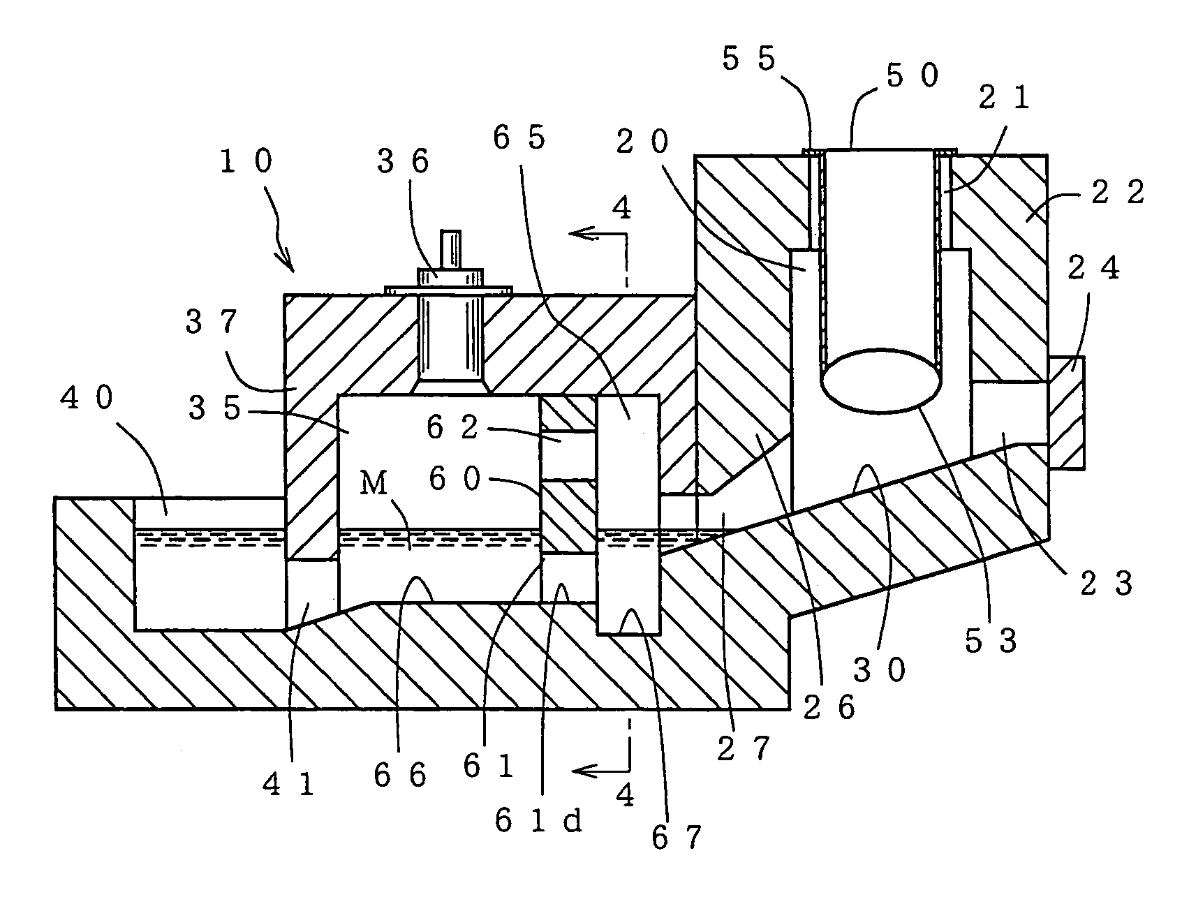
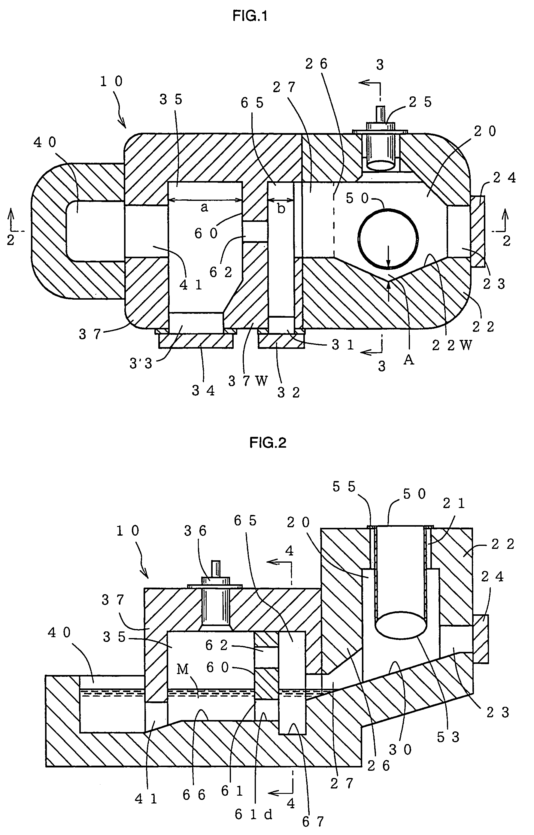
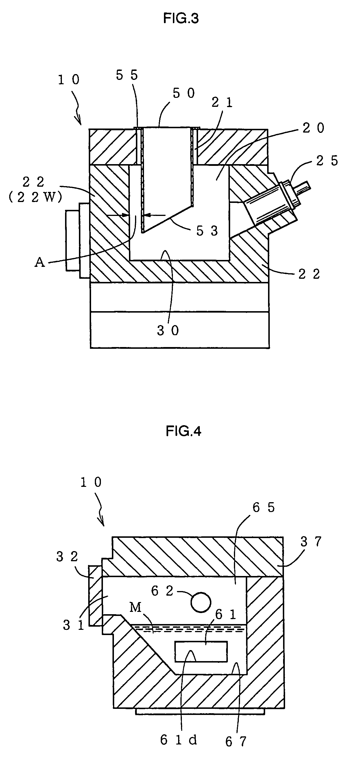
[0028]A metal melting furnace 10 according to an embodiment of the present invention is a furnace in which an aluminum for casting is molten and held. As can be seen in FIGS. 1 through 4, a meltable material is introduced in a preheating flue 20 which is provided, on its upper end, a material inlet opening 21 (which also serves as an air discharge opening) and, on its lower end, with an inclined hearth 30. The introduced material is heated and molten by a melting burner 25 which is oriented toward the lower portion of the preheating flue 20.

[0029]The molten metal is introduced into a molten metal reservoir 35 from the inclined hearth 30. In the molten metal reservoir 35, the internal molten metal M is heated by a temperature maintaining burner 36 to maintain the molten metal at a predetermined temperature. The metal melting furnace constructed as above is generally called a dry hearth furnace.

[0030]In the drawings, numeral 22 and 26 designate the furnace walls which constitute the p...


PUM

PropertyMeasurementUnit
Poweraaaaaaaaaa
Heightaaaaaaaaaa

Abstract

In a metal melting furnace, a separation wall 60 is provided between an inclined hearth 30 and a molten metal reservoir 35 to define a molten metal processing portion 65. The separation wall is provided with a connecting passage 61 for the molten metal, between the molten metal reservoir and the molten metal processing portion, at a height level higher than a bottom surface 67 of the molten metal processing portion. The separation wall is also provided on its upper portion with an exhaust gas passage which permits exhaust gas discharged from the molten metal reservoir to pass therethrough. An inspection opening 31 with a door 32 is provided in a furnace wall surface 37W to open into the molten metal processing portion.

Description

BACKGROUND OF THE INVENTION[0001]1. Field of the Invention[0002]The present invention relates to a melting furnace for a metal such as aluminum.[0003]2. Description of the Related Art[0004]The inventor of the present invention has proposed a metal melting furnace 100 as shown in FIGS. 5 to 7. In FIGS. 5 to 7, a metal melting furnace is comprised of a preheating flue 120 which is provided, on its upper end, with a material inlet opening 121 through which a meltable material is introduced in the preheating flue 120 and, on its lower end, with an inclined hearth 130. The meltable material (metal) introduced in the preheating flue 120 is heated and molten by a melting burner 125 which is oriented toward the lower end of the preheating flue 120. The molten metal is introduced in a molten metal reservoir 135 through the inclined hearth 130.[0005]The temperature of the molten metal M in the reservoir 135 is maintained at a predetermined value by a temperature maintaining burner 136. A melt...

Claims


Application Information

Patent Timeline
IPC IPC(8): C21C7/00C21B7/00F27B3/04C21C5/56C22B21/00C22B21/06F27B3/18F27B3/20F27D3/10F27D13/00
CPCC21C5/567C22B21/0084C22B21/06F27B3/18F27B3/205F27B3/04Y10S266/90
Inventor NAKASHIMA, MITSUKANE
Owner MEICHU
Why Eureka
Try Eureka