
Magnetic resonance imaging system

a magnetic resonance imaging and magnetic resonance technology, applied in the field of magnetic resonance imaging apparatus, can solve the problems of insufficient imaging speed, inability to increase the imaging speed, and the s/n ratio of the image deteriorates on the lines along which the sensitivity distribution of the two sub-coils is similar

Inactive Publication Date: 2006-06-13
HITACHI MEDICAL CORP
View PDF7 Cites 21 Cited by
  • Summary
  • Abstract
  • Description
  • Claims
  • Application Information

AI Technical Summary

Problems solved by technology

Also, when the values of f1A / f1B and f2A / f2B are not completely the same, but are close to each other, that is, when the sensitivity distributions of the two sub-coils are similar, a problem occurs in that, when image reconstruction is performed, the S / N ratio of the image is deteriorated on the lines along which the sensitivity distributions of the two sub-coils are similar.
However, in the structure proposed hitherto, there is a problem in that the imaging speed-up ratio can only be improved by twice when the phase-encoding direction is set to the static magnetic field direction.
That is, when imaging a transverse plane which is often used in the imaging of the heart, there is a problem in that the imaging speed cannot be sufficiently raised when the phase-encoding direction is set to a direction of chest-to-back (static magnetic field direction).
However, in the imaging of the heart, there is a problem that the user's need for freely setting the phase-encoding direction in order to reduce artifacts of blood flow is not satisfied.
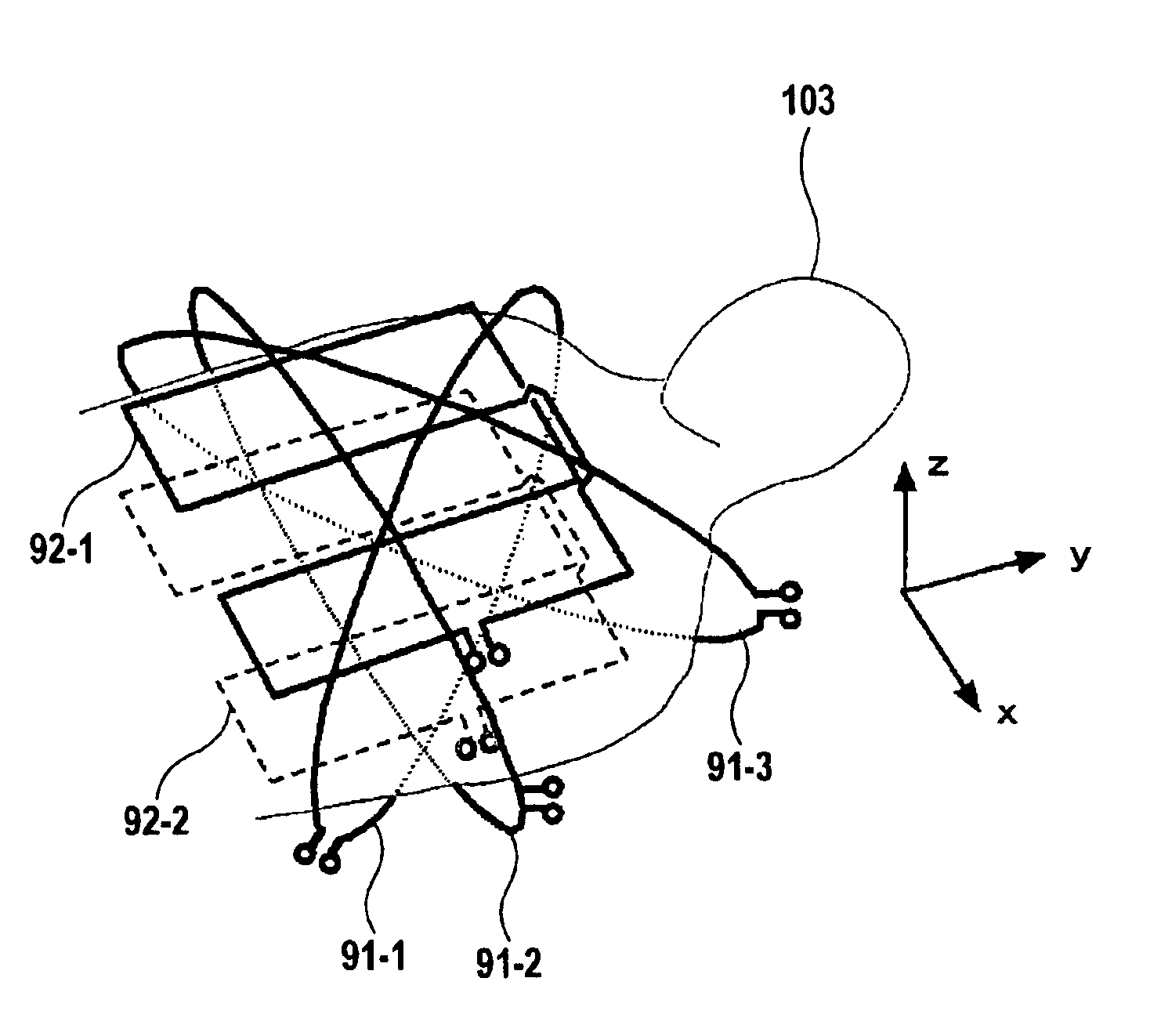
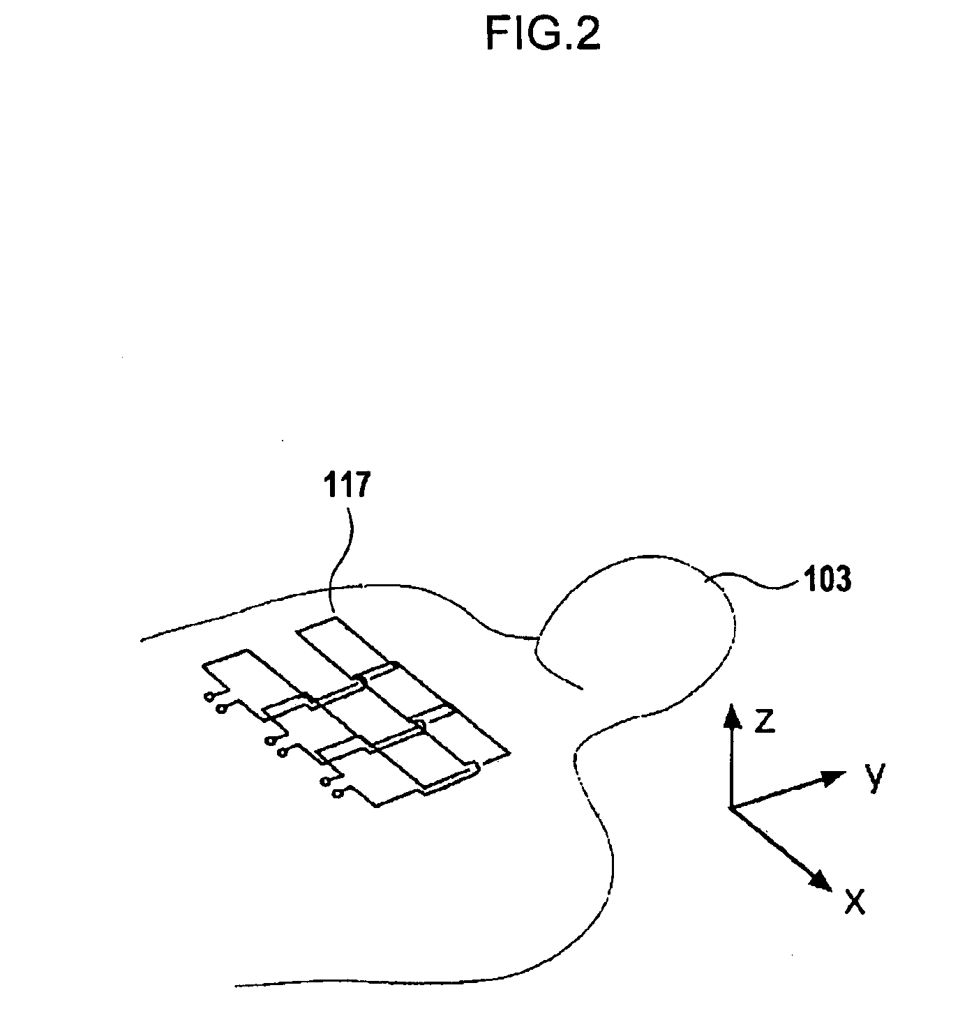
However, since the figure-eight coils 117 have a sensitivity only above and below the conductors 41 and 42 in FIG. 4, there is a problem that the sensitivity of all sub-coils, except in the portion below the conductors 41 and 42, is significantly deteriorated when performing imaging on a coronal plane (xy plane) with the arrangement of the coils shown in FIG.

Method used


Image

  • Magnetic resonance imaging system
  • Magnetic resonance imaging system
  • Magnetic resonance imaging system

Examples


Embodiment Construction

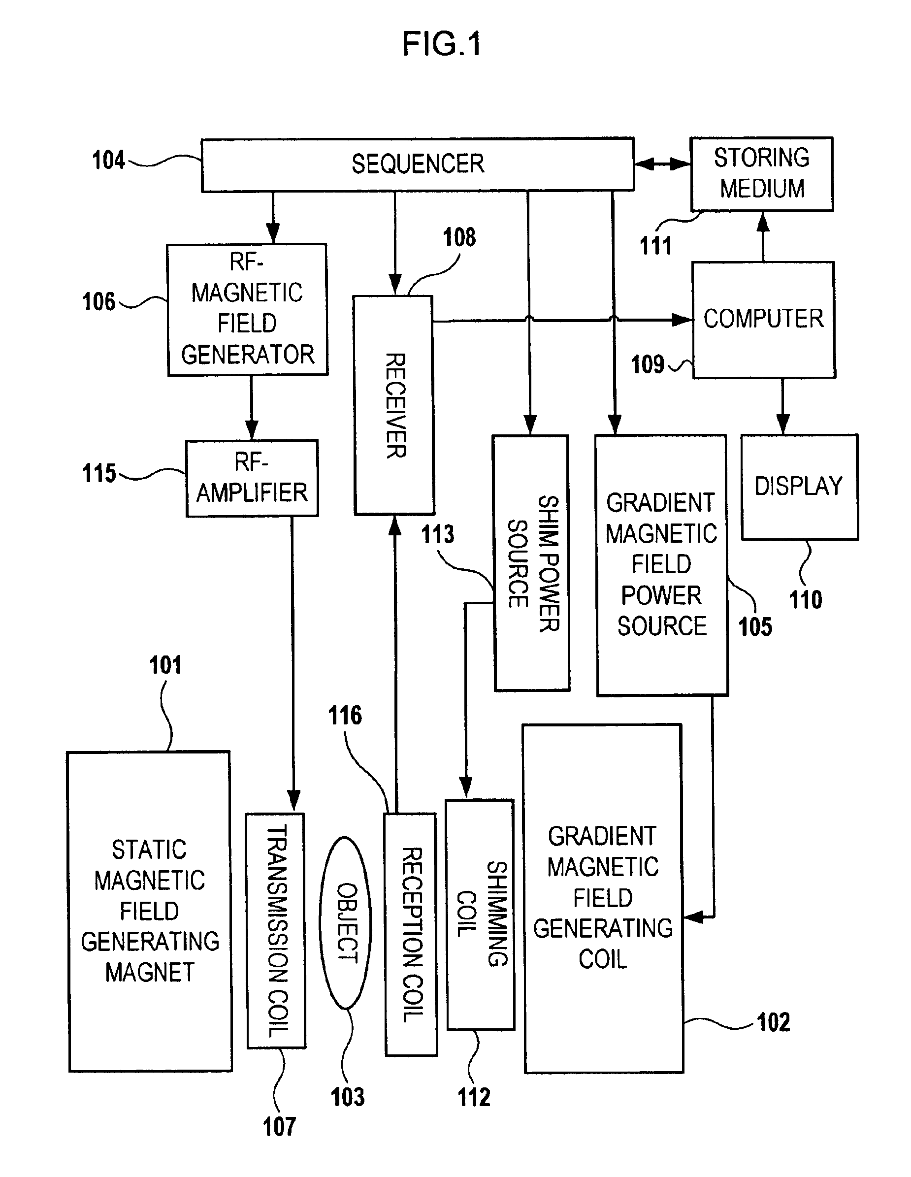
[0064]FIG. 1 is a block diagram showing an example of the structure of an MRI apparatus according to the present invention. As shown in FIG. 1, an object 103 is placed in a magnetic-field space, where a static magnetic field generated by a magnet 101 and gradient magnetic fields generated by a coil 102 are superposed. Generally, the gradient magnetic field generating coil 102 includes gradient magnetic field coils located on three axes intersecting with one another at right angles.

[0065]A sequencer 104 transmits an instruction to a gradient magnetic field power source 105 and a radio-frequency magnetic field (RF pulse) generator 106 such that gradient magnetic fields and an RF pulse are generated by the gradient magnetic field coil 102 and a transmission coil 107, respectively. Usually, the RF pulse output by the radio-frequency magnetic field generator 106 is amplified by an RF power amplifier 115, and it is applied to the object 103 from the transmission RF coil 107. Nuclear magne...


PUM


Abstract

To provide a diagnostic apparatus utilizing nuclear magnetic resonance suitable for interventional MRI which is not limited as to selection of an imaging section and an phase-encoding axis, the reception coil thereof includes three loop coils arranged so as to surround an object to be examined and to be within a plane including a line segment parallel to a static magnetic field direction, and two surface coils arranged in the vicinity of the surface of the object within a plane including a line segment perpendicular to the static magnetic field direction. In the reception coil, two or more sub-coils have nonuniform sensitivity profiles along an arbitrary axis. Therefore, the reception coil configured to have sensitivity throughout the imaging areas can be realized.

Description

FIELD OF THE INVENTION[0001]The present invention relates to a magnetic resonance imaging (MRI) apparatus; and, more particularly, the invention relates to an MRI apparatus that is suitable for interventional MRI.BACKGROUND OF THE INVENTION[0002]An MRI apparatus is characterized in that high tissue-contrast resolution can be obtained, and desired tomograms can be obtained; and, such an apparatus has no invasiveness, for example. The application of an MRI apparatus, having such characteristics, not only to diagnostic imaging, but also to interventional MRI, such as is used in connection with the guiding of a biopsy needle, the monitoring of therapy, the guiding of an endoscope and a catheter, and the like, has been drawing increased attention. In interventional MRI, a device, such as a biopsy needle and a catheter, is inserted in the body of the object to be examined, while an operator (a doctor) observes the position of the device using MR images. That is, the device in the object, ...

Claims


Application Information

Patent Timeline
Patent Type & Authority Patents(United States)
IPC IPC(8): G01V3/00G01R33/34A61B5/055G01R33/3415
CPCG01R33/3415A61B5/055
Inventor OCHI, HISAAKITANIGUCHI, YOTAKAHASHI, TETSUHIKOOKAJIMA, KEN'ICHI
Owner HITACHI MEDICAL CORP
Learn More