
Locating items with flickering lamps

Inactive Publication Date: 2006-06-13
BROMER NICK
View PDF6 Cites 37 Cited by
  • Summary
  • Abstract
  • Description
  • Claims
  • Application Information

AI Technical Summary

Benefits of technology

[0010]Another application is in finding files (dossiers, folders, etc.) in an office. Office files are now commonly bar coded, which makes it easy to verify the identity of that file with a scanner. But the bar codes do not help in locating a lost file. With the invention, each file includes a device that flickers at an interval, such as every few seconds, so that a stack of files flashes like fireflies at night, with each flash being the flicker. Each file flickers a pattern that identifies that particular file, or the group (subset) of files to which that particular item belongs; preferably, the flicker pattern includes different fields that allow searching for a subset, a superset, or an individual file, as needed. To find a flickering file, a passive hand-held detector with a photodiode can be programmed to beep when it “sees” a particular flicker pattern. When aimed at a stack of flickering files, the detector will beep after a second or two if the missing file is there. Then the detector can be moved in so that its angle of detection covers a smaller area of the stack of files, and the file thereby located precisely. This will prevent loss of files by mis-filing, which can be a problem in places, such as law firms, with many files.

Problems solved by technology

But the bar codes do not help in locating a lost file.

Method used


Image

  • Locating items with flickering lamps
  • Locating items with flickering lamps

Examples


Embodiment Construction

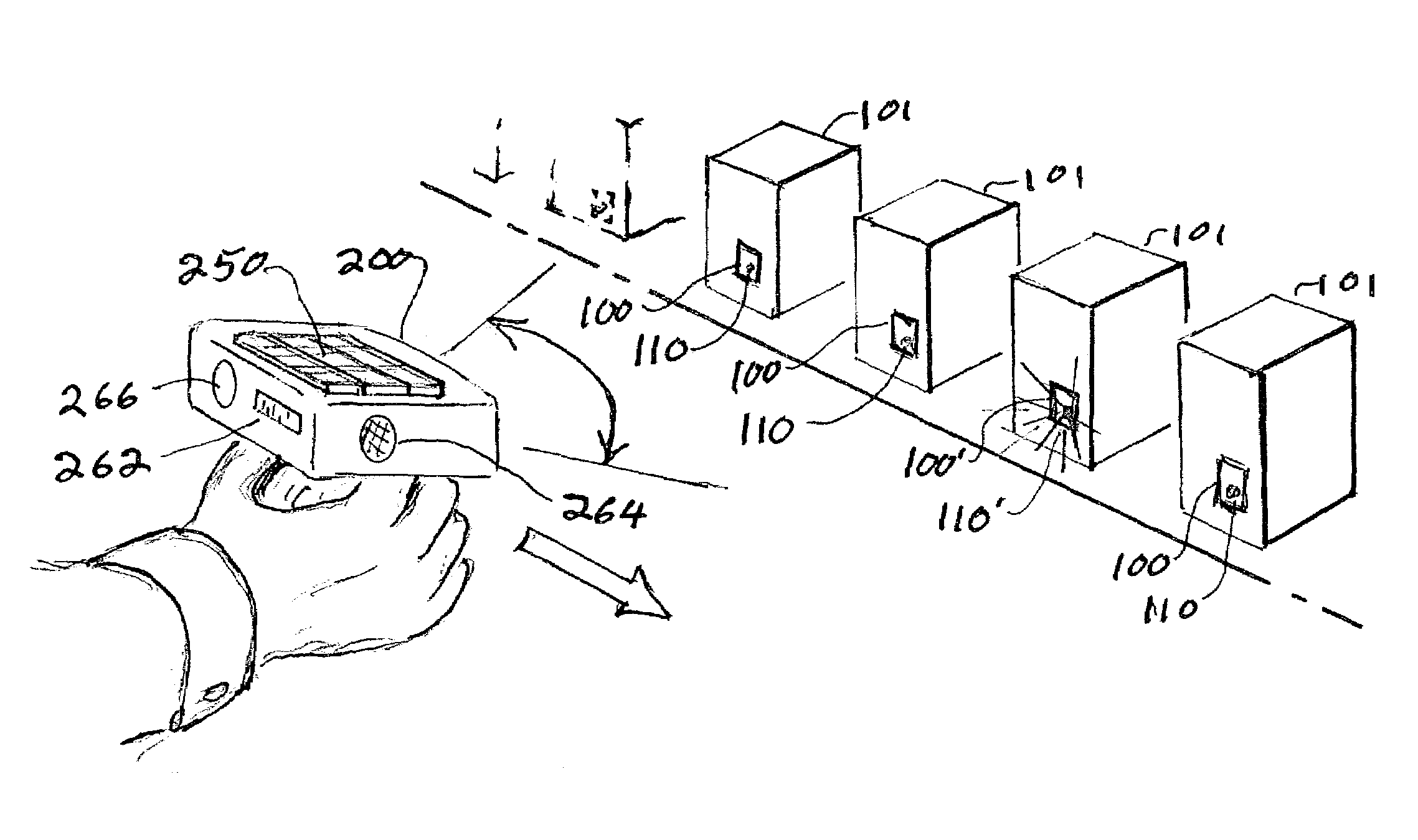
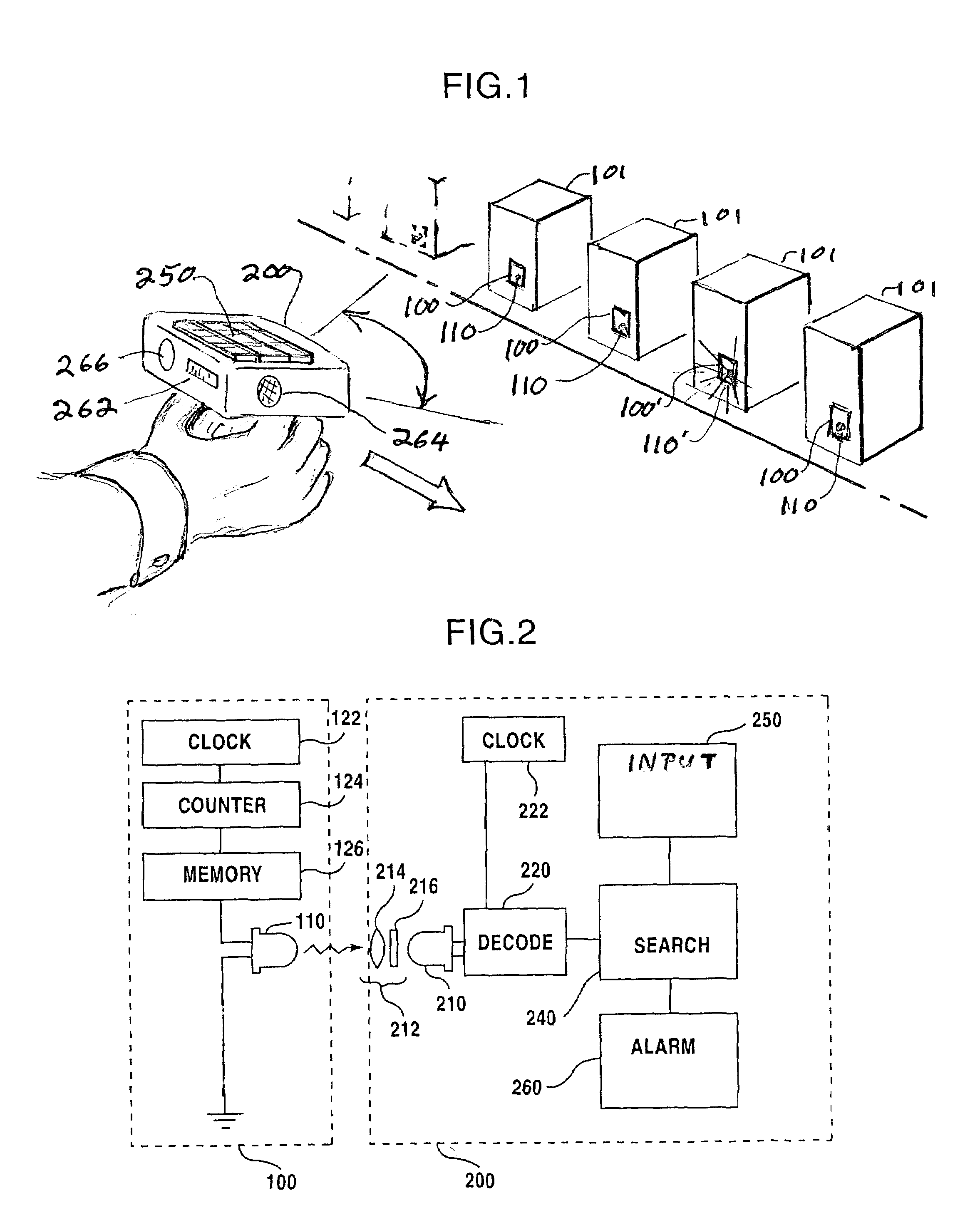
[0015]FIG. 1 shows a preferred embodiment of the invention. At least some (preferably all) of a collection of items 101 are equipped with attached lamp units 100 with a lamp 110. At the instant depicted in the drawing, the lamp 110′ of one of the lamp units 100′ is emitting a flicker of light (visible, infrared, or ultraviolet); this is illustrated by rays from the lamp 110′. At a future time, the lamps of the other units may radiate light; this is discussed below. The flickering light is in a pattern that encodes an identifier of the item 101.

[0016]A detector 200 is shown being held near the items 101. The detector has a location detection range indicated by the solid, curved, double-headed arrow. As is explained below, if an item 101 flickers within the range of the detector, the presence of the item at that location will be registered. The detector 200 has a light sensor (not shown in FIG. 1), for example a photodiode, that turns the flickering light into a signal voltage that is...


PUM


Abstract

Items, including lost items or items out of place, can be located by attaching flickering LED's to them and moving about with a detector that registers the presence of the desired item or items by decoding the flickers. The flickers can substitute for, or augment, ordinary printed bar codes, and can use the same encoding so that the temporal pattern of flickering corresponds to the spatial pattern of black and white stripes in the printed bar code. The flickering items can be registered from a distance and from among a large group of other flickering items.

Description

CROSS REFERENCE TO RELATED APPLICATION[0001]This application is a division of application Ser. No. 09 / 987,241, filed by the same Applicant on Nov. 14, 2001, now U.S. Pat. No. 6,476,715 and entitled LAND VEHICLE IDENTIFICATION BY FLICKERING LAMPS. The entire contents of application Ser. No. 09 / 987,241 are entirely incorporated herein by reference, including those portions of application Ser. No. 09 / 987,241 that were incorporated therein by reference and did not appear in the text of application Ser. No. 09 / 987,241. The Applicant's application Ser. No. 09 / 987,341 claimed benefit of the filing date of application Ser. No. 60 / 290,687, and also incorporated the whole disclosure of that provisional application Ser. No. 60 / 290,687 by reference. Therefore this divisional application incorporates the subject matter of application Ser. No. 60 / 290,687. Under MPEP §608.01(p)B, the present application has benefit of the filing date of application Ser. No. 60 / 290,687, which was May 15, 2001.REVIE...

Claims


Application Information

Patent Timeline
IPC IPC(8): G08B5/00B60R13/10G08G1/017
CPCG08G1/017G06Q10/087B60R25/00B60R13/10
Inventor BROMER, NICK
Owner BROMER NICK
Learn More