Electronically scanned beam display

a beam display and beam technology, applied in the field of electric beam display, can solve the problems of large power consumption, unsuitable portable or head-mounted applications, and device limitations,

Inactive Publication Date: 2006-06-13
MICROVISION
View PDF14 Cites 91 Cited by
  • Summary
  • Abstract
  • Description
  • Claims
  • Application Information

AI Technical Summary

Problems solved by technology

Such devices suffer from several limitations.
For example, CRTs are bulky and consume substantial amounts of power, making them undesirable for portable or head-mounted applications.
Such screens have limited use in head mounted applications or in applications where the display is intended to occupy only a small portion of a user's field of view.
One difficulty with such displays is raster pi...

Method used


Image

  • Electronically scanned beam display
  • Electronically scanned beam display
  • Electronically scanned beam display

Examples


Embodiment Construction

Overview

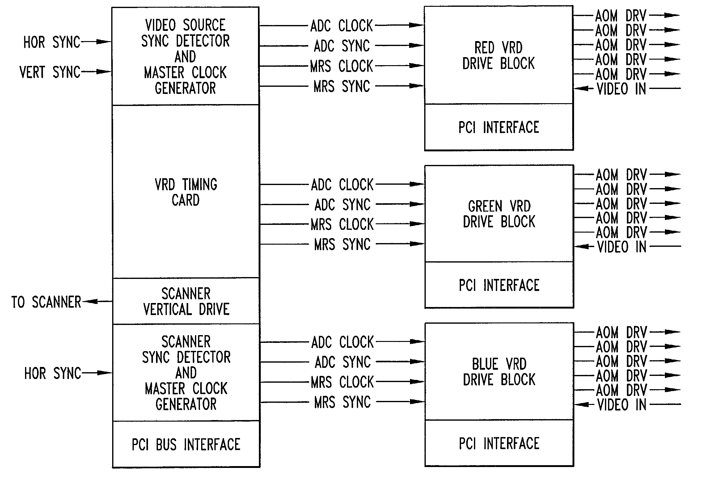
[0039]As described in U.S. Pat. No. 6,140,979 of Gerhard et al., a scanned beam display includes red, green, and blue light sources, such as lasers or LEDs. The lasers or LEDs may be modulated directly or indirectly. Where the modulators are external to the light source, the light may be divided into a plurality of beams, each having a respective beam modulator.

[0040]One component of the display is an electronic control system that accepts video inputs from an image source and other signals, such as control or sense signals. Responsive to the video inputs and other signals, the control circuit produces output signals that drive the light sources or modulators as the case may be.

[0041]In one embodiment, the input signals are analog RGB signals with separate digital horizontal and vertical syncs corresponding to a typical screen format such as SXGA, having 1280 pixels (“pels”)×1024 lines with 60 Hz refresh rate. In a non-interlaced format, the corresponding input dot clock is ...


PUM


Abstract

A scanning control circuit generates a clock signal corresponding to an expected scan timing of a resonant scanner. In one approach, the control circuit uses a pair of direct digital synthesis (DDS) integrated circuits. A first DDS chip provides a system clock that is synchronized to the monitored period of the scanner. A second DDS chip generates a frequency chirped signal that has a frequency profile corresponding to a desired pixel clock timing. To control phase precisely, four complementary clock signals are weighted and mixed at light source drivers to produce relative phase shifts for different light sources.

Description

CROSS REFERENCE TO RELATED APPLICATIONS[0001]This application claims benefit of U.S. Provisional Application No. 60 / 282,719; filed Apr. 9. 2001; entitled ELECTRONICALLY SCANNED BEAM DISPLAY: invented by Gregory Scott Bright, et al.STATEMENT OF GOVERNMENT RIGHTS[0002]The invention was made with Government support under Contract No. DAAH10-99-C-0034 awarded by the Aviation Applied Technology Directorate of the Department of the Army. The Government may have certain rights in the invention.BACKGROUND OF THE INVENTION[0003]A variety of techniques are available for providing visual displays of graphical or video images to a user. For example, cathode ray tube type displays (CRTs), such as televisions and computer monitors are very common. Such devices suffer from several limitations. For example, CRTs are bulky and consume substantial amounts of power, making them undesirable for portable or head-mounted applications.[0004]Flat panel displays, such as liquid crystal displays and field em...

Claims


Application Information

Patent Timeline
IPC IPC(8): G09G5/00G02B26/10G02B27/01G09G3/00H04N3/08H04N5/04H04N5/06H04N5/12H04N9/31H04N9/64
CPCG02B27/017G09G3/001G09G3/025H04N3/08H04N9/641H04N9/3132H04N5/06H04N5/126H04N5/04
Inventor BRIGHT, GREGORY SCOTTSTRAKA, SCOTT W.BLACK, PHILIP C.MOORE, JAMES G.LEWIS, JOHN R.UREY, HAKANTEGREENE, CLARENCE T.
Owner MICROVISION
Why Eureka
Try Eureka