
Projection display apparatus and system

a projection display and projection display technology, applied in the direction of identification means, instruments, static indicating devices, etc., can solve the problems of increasing the cost, complicated user operation making the presentation, and the limitation of the number of connectors provided in the small-sized portable personal computer, so as to improve the operating performance of the system and improve the system. the effect of system performan

Inactive Publication Date: 2006-06-13
SONY CORP
View PDF9 Cites 36 Cited by
  • Summary
  • Abstract
  • Description
  • Claims
  • Application Information

AI Technical Summary

Benefits of technology

The present invention provides a projection display apparatus and system that improve the operability of controlling a displayed picture using a control device. The apparatus and system connect to a control device through a serial interface, allowing for data transmission and display control signals. The apparatus includes display means, input / output means, and display control means for controlling the picture shown on the display screen. The system also allows for the control device and external peripheral equipment to input / output data and control the picture shown on the projection display apparatus. The technical effect of this invention is to improve the user experience and ease of use for controlling the displayed picture.

Problems solved by technology

However, there is a limit in the number of connectors provided in the small-sized portable personal computer, such that the connector is taken up by the projector control cable used for interconnecting the projector and the portable personal computer to render it impossible to make connections to other devices, such as a mouse.
Moreover, if, in making presentation using the above-described display system in e.g., a small conference hall, the pointer control employing a remote controller emitting the IR light is used, the user operation making the presentation tends to be complicated.
In addition, if, in the conventional display system, employing a projector, plural projectors are used, dedicated switchers etc., adapted for coping with e.g., RS 485, need to be used, thus raising the cost.

Method used


Image

  • Projection display apparatus and system
  • Projection display apparatus and system
  • Projection display apparatus and system

Examples


Embodiment Construction

[0030]Referring to the drawings, preferred embodiments of according to the present invention will be explained in detail.

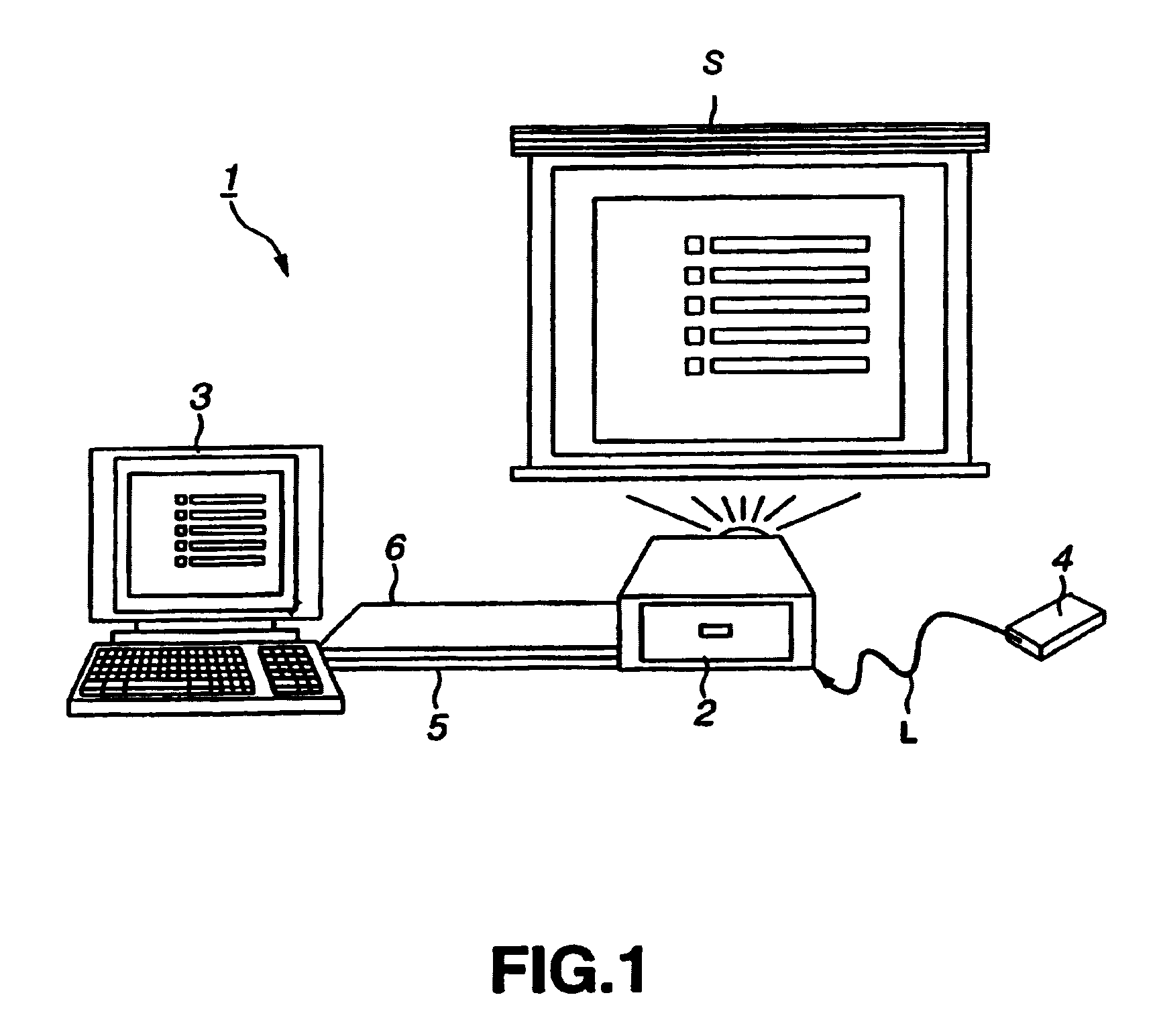
[0031]The present invention is applied to a projection display system 1 configured as shown for example in FIG. 1.

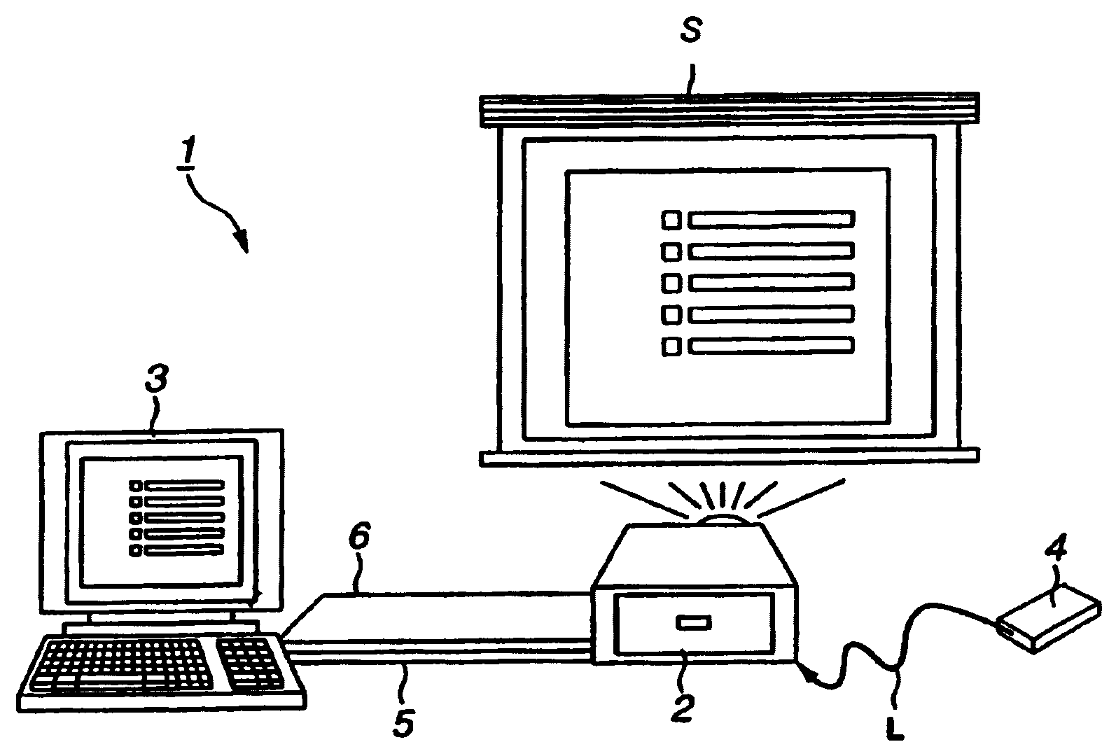
[0032]This projection display system 1 is made up of a projector 2 and a control device 3 controlling the projector 2 and which is connected over a USB (Universal Serial Bus) cable 5 to permit bidirectional packet transmission / reception. The control device 3 controls the projector 2 and performs display control responsive to USB mouse signals from a remote controller 4. In this projection display system 1, the control device 3 and the projector 2 are interconnected over an RGB (red, green and blue) cable 6 to send display data from the control device 3 to the projector 2 to project light on a display screen 5 to display an image thereon.

[0033]The projector 2 includes therein an optical system and so forth and, based on display data supplied from the co...


PUM


Abstract

An image controlling system in which an image to be displayed is controlled by a control device is to be improved in its operating performance. A control device 3 and a projector 2 are interconnected over a USB cable 5 and an RGB cable 6 to make bi-directional data transmission / reception to display a picture by the projector 2 on a display screen S. The projector 2 includes a projection display unit 18 fed with display data from the control device 3 to project light to display a picture represented by the display data, a hub 11 connected to the control device 3 and to a USB device to make data input / output based on the supplementary information and a display controller19 for controlling a picture demonstrated by the projection display unit 18 based on a display control signal generated by the control device 3. The control device includes a connector 32, connected to the projector 2, and a controller 33 for outputting the control signal and the display data to have a picture displayed by the projector 2.

Description

BACKGROUND OF THE INVENTION[0001]1. Field of the Invention[0002]This invention relates to a projection display apparatus and a projection display system in which data is furnished from outside and light is projected to display an image.[0003]2. Description of Related Art[0004]There is such a display system in which a liquid crystal projector is controlled by a personal computer as a control device for making presentation. In such display system, the projector is controlled by the personal computer to project an image on the screen.[0005]When a pointer position displayed along with an image using this display system is moved to make presentation, a projector and a remote controller making infrared communication are frequently used. That is, the remote controller is actuated by a user to generate an actuating input signal to output the signal as the IR light to an IR light receiving portion of the projector. This causes the projector to output an actuating input signal over a dedicate...

Claims


Application Information

Patent Timeline
Patent Type & Authority Patents(United States)
IPC IPC(8): G09G5/00G06F3/033G06F3/153G06F3/14G06F13/38G09F9/00G09F13/04
CPCG06F3/033G09G5/006G06F3/14
Inventor NOGUCHI, KUNIHIKO
Owner SONY CORP
Learn More