Capsule type medical device

a medical device and capsule technology, applied in the field of capsule medical devices, can solve the problems of shortening the usable time of capsules, unable to receive information fully by the external device side, and not considering the proper transmission of living body information from the capsule side to the external device sid

Inactive Publication Date: 2006-06-13
OLYMPUS CORP
View PDF10 Cites 38 Cited by
  • Summary
  • Abstract
  • Description
  • Claims
  • Application Information

AI Technical Summary

Benefits of technology

[0013]Accordingly, it is an object of the present invention to provide a capsule type medical device, which allows the detection for setting proper transmission power and the like.
[0014]It is another object of the present invention to provide a capsule type medical device, which can send information by using proper transmission power.
[0015]There is provided a capsule type medical device, including a capsule inserted into a living body, having a living body information detecting device for obtaining living body information, an external unit located outside of the living body, a first sending and receiving circuit provided in the external unit for signal sending and receiving, a first antenna connected to the first sending and receiving circuit, a second sending and receiving circuit provided in the capsule for signal sending and receiving, a second antenna connected to the second sending and receiving circuit, and a radio wave strength detecting circuit for detecting radio wave strength when a signal sent from the first sending and receiving circuit side through the first antenna is received by the second sending and receiving circuit through the second antenna. Thus, when information of the radio wave strength detected by the radio wave strength detecting circuit and living body information are sent, proper transmission power can be set.

Problems solved by technology

However, the example of the related art does not consider the proper transmission of living body information from the capsule side to the external device side.
In this case, electric energy in a battery built in the capsule is consumed largely, thus shortening the capsule usable time.
In this case, however, the information cannot be received by the external device side fully.
However, like the case of the first technology of the related art, it is not arranged so as to set the proper transmission power on the capsule side.

Method used


Image

  • Capsule type medical device
  • Capsule type medical device
  • Capsule type medical device

Examples


first embodiment

[0045]A first embodiment of the present invention will be described with reference to FIGS. 1A to 8B.

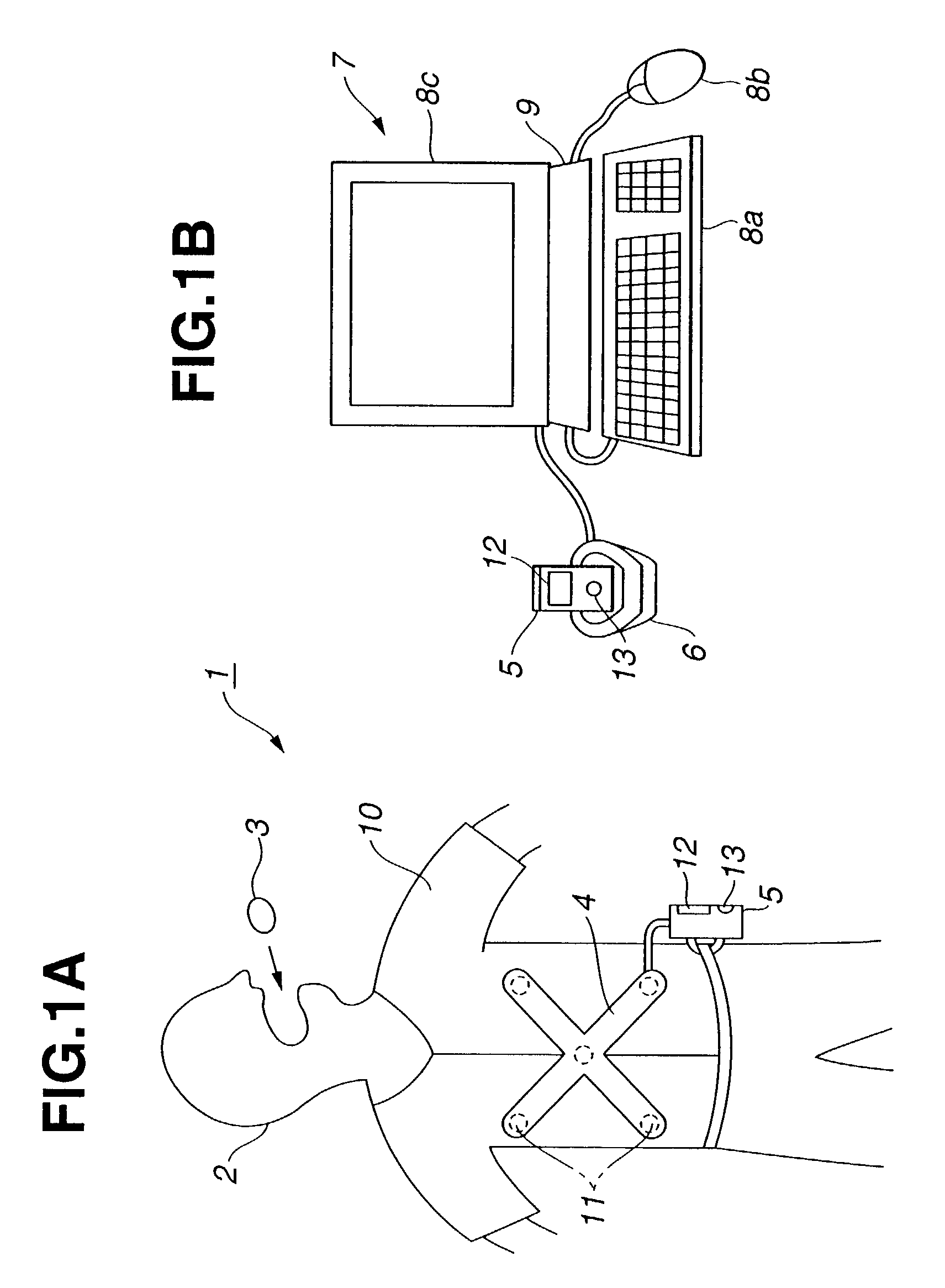
[0046]As shown in FIG. 1A, a capsule type endoscope device 1 according to the first embodiment of the present invention includes a capsule type endoscope 3 for detecting the inside of a body cavity, which is swallowed by a patient 2, and an external unit 5, which is located outside of the patient 2 and is connected to an antenna unit 4 which receives by wireless means image information captured by the capsule type endoscope 3.

[0047]As shown in FIG. 1B, the external unit 5 is attached to a cradle 6 and is electrically connected to a terminal device 7 such as a personal computer. The terminal device 7 can capture into a terminal body 9 an image stored in the external unit 5 by manipulating an input / manipulation device such as a keyboard 8a and a mouse 8b and can display the captured image on a monitor portion 8c.

[0048]As shown in FIG. 1A, when the patient 2 swallows the capsule type e...

second embodiment

[0122]A second embodiment of the present invention will be described with reference to FIG. 9. FIG. 9 shows the configuration of a main portion of a capsule-type medical device 1B according to the second embodiment.

[0123]The capsule-type medical device 1B includes a capsule body 3B having a detector 51 such as a pH sensor for obtaining living body information and an external unit 5B for receiving and storing living body information from the capsule body 3B.

[0124]The capsule body 3B in the capsule endoscope 3 in FIG. 2 includes a detector 51 such as pH sensor instead of an illumination and image pickup means. Further, the external unit 5B has a function for storing information of the detector 51.

[0125]As shown in FIG. 9, the external unit 5B further includes an antenna ID generating circuit 52 in the configuration in FIG. 4. In other words, according to this embodiment, unique antennas are assigned to multiple antennas 11a to 11d, respectively. Thus, when transmission is performed fr...

third embodiment

[0139]Next, a third embodiment of the present invention will be described with reference to FIG. 11. FIG. 11 shows the configuration of a main portion of a capsule-type medical device ID of the third embodiment.

[0140]An external unit 5D included in the capsule-type medical device ID shown in FIG. 11 has the same structure of that of the external unit 5 in FIG. 4. A capsule body 3D has basically the same configuration as that of the capsule endoscope 3 in FIG. 3.

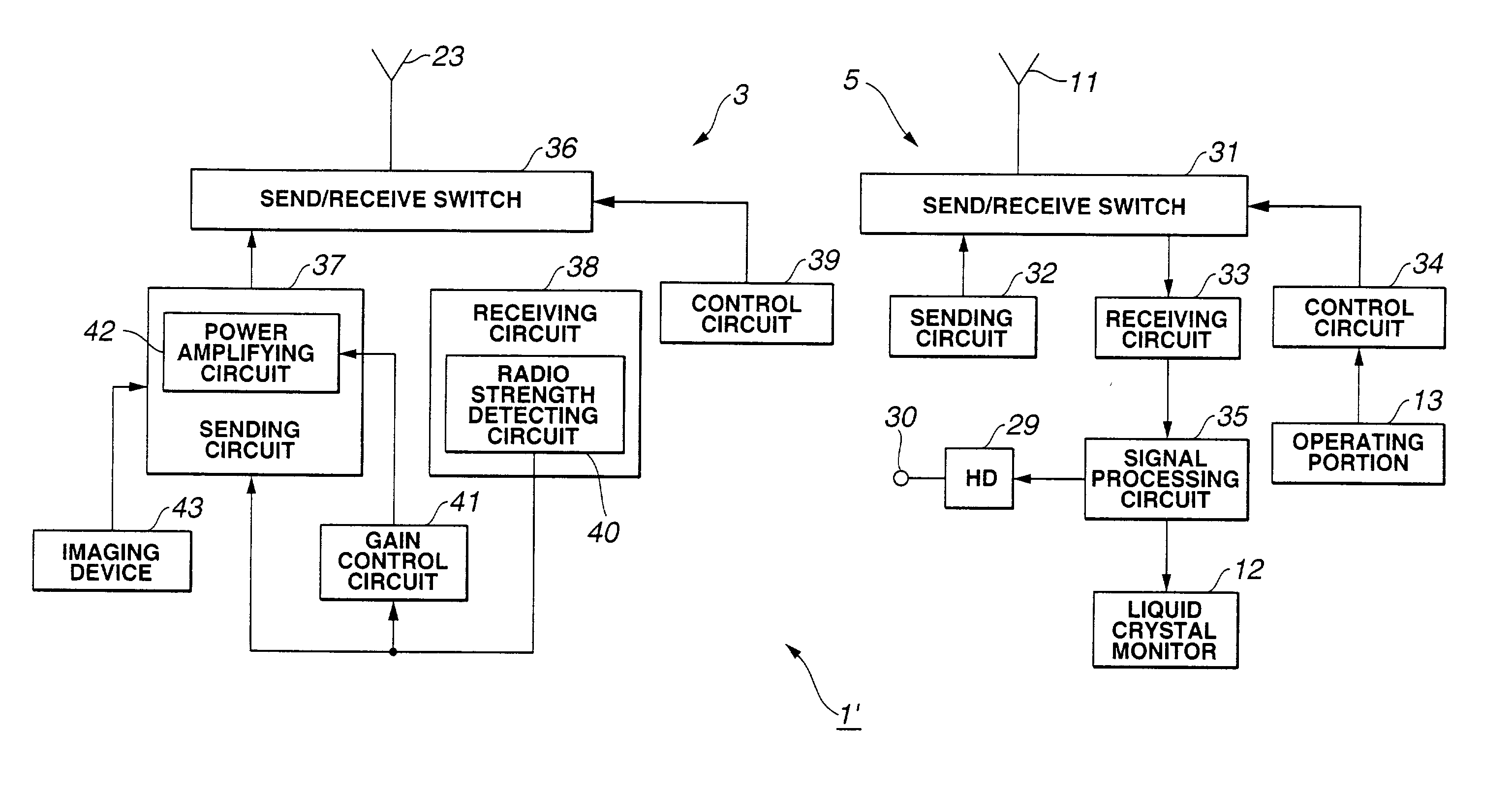
[0141]In other words, the capsule body 3D has the configuration having a power amplifying circuit 57 for performing power amplification between the sending circuit 37 and the send / receive switch 36 and a gain control circuit 58 for controlling gain for power amplification by the power amplifying circuit 57 in addition to the configuration of the capsule body 3B in FIG. 9.

[0142]In this embodiment, gain for power amplification by the power amplifying circuit 57 is controlled through the gain control circuit 58 based on the outp...


PUM


Abstract

Signals are sent by radio waves from a single or multiple antennas provided in an external unit located outside of a living body to a capsule inserted into a living body to obtain living body information. The signals are received by the antenna on the capsule side and the radio wave strength data is obtained. Based on the radio wave strength data, living body information is sent from the capsule side to the external unit by using a transmission power suitable for the transmission. The radio wave strength data is sent to the external unit side, and the external unit side receives living body information by selecting and using an antenna, which can receive data with the highest radio wave strength.

Description

[0001]This application claims benefit of Japanese Application No. 2001-341101 filed on Nov. 6, 2001, the contents of which are incorporated by this reference.BACKGROUND OF THE INVENTION[0002]1. Field of the Invention[0003]The present invention relates to a capsule type medical device including a swallowable capsule and an external unit of receiving living body information sent from the capsule.[0004]2. Description of the Related Art[0005]Recently, a capsule type device has been proposed whereby a capsule body in capsule form is inserted into a body cavity for examination.[0006]For example, according to a first technology of the related art, disclosed in Japanese Unexamined Patent Application Publication No. 7-111985, a spherical capsule, which is divided into two, is used to communicate living body information to an external device via a communication unit.[0007]However, the example of the related art does not consider the proper transmission of living body information from the caps...

Claims


Application Information

Patent Timeline
Patent Type & Authority Patents(United States)
IPC IPC(8): H04N7/18A61B1/00A61B1/05A61B1/273A61B5/00A61B5/07A61B8/12
CPCA61B1/00016H04N7/185A61B1/00036A61B1/041A61B1/0676A61B1/0684A61B5/0031A61B5/073A61B5/14539A61B5/4839A61B8/56A61B1/00029A61B1/00032A61B8/12A61B8/4472A61B2560/0209A61B2560/0219
Inventor FUJITA, MANABUHOMAN, MASATOSHI
Owner OLYMPUS CORP
Why Eureka
Try Eureka