Computed tomography with increased field of view

a computed tomography and field of view technology, applied in tomography, material analysis using wave/particle radiation, instruments, etc., can solve the problems of increasing the size of the array, introducing significant technical difficulty and expense, and reconstructed three-dimensional representation artifacts and errors, etc., to achieve increased fov, increased fov, and larger detector (or source) array size

Active Publication Date: 2006-06-13
AIRDRIE PARTNERS I LP +1
View PDF18 Cites 178 Cited by
  • Summary
  • Abstract
  • Description
  • Claims
  • Application Information

AI Technical Summary

Benefits of technology

[0007]The present invention provides improved CT systems and methods that enjoy substantially increased FOV. The diameter of the in-plane FOV of CT systems according to the present invention can be larger than th

Problems solved by technology

Although the FOV of a CT system can be increased using a larger detector array, increasing the size of the array often introduces significant technical difficulty and expense.
Another drawback of this CT system design is that the source and detector must rotate through a large angle to acquire images from a sufficiently large range of angles.
If a patient moves during the rotation, the image data from different angles will not be consistent, resulting in artifacts and errors in the reconstructed three-dimensional representation.
However, the field of view 326 of this s

Method used


Image

  • Computed tomography with increased field of view
  • Computed tomography with increased field of view
  • Computed tomography with increased field of view

Examples


Embodiment Construction

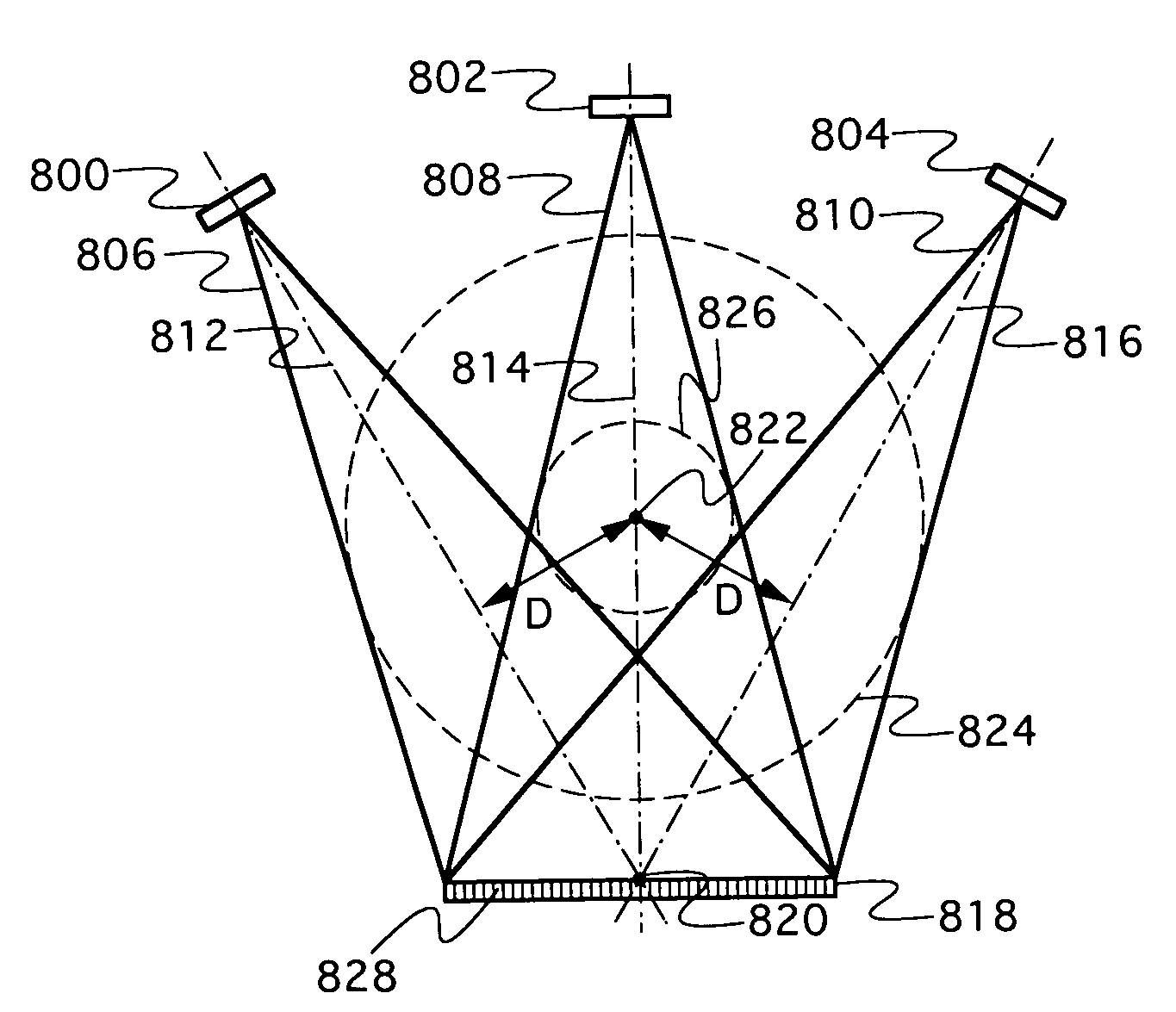
[0019]A volumetric CT system according to one embodiment of the invention is illustrated in FIG. 5. Two x-ray point sources 500 and 502 emit corresponding fan beams 504 and 506 at a single detector array 508 at different corresponding times. X-ray image data is acquired from the detector array 508 to reconstruct a representation of an object of interest. The x-ray point sources 500 and 502, as well as the detector 508 are rotated together around a rotational axis 520 of the system. Consequently, fan beams 504 and 506 also rotate about axis 520. The fan beams 504 and 506 have corresponding central rays 510 and 512 that bisect the detector array 508 at a midpoint 514. Because the multiple fan beams are directed toward a common detector array from sources having different locations, the central rays 510 and 512 have different angular orientations and are radially offset from the rotational axis 520 by a significant offset distance D, resulting in a FOV 516 for the system which is signi...


PUM


Abstract

A volumetric computed tomography system with a large field of view has, in a forward geometry implementation, multiple x-ray point sources emitting corresponding fan beams at a single detector array. The central ray of at least one of the fan beams is radially offset from the axis of rotation of the system by an offset distance D. Consequently, the diameter of the in-plane field of view provided by the fan beams may be larger than in a conventional CT scanner. Any number of point sources may be used. Analogous systems may be implemented with an inverse geometry so that a single source array emits multiple fan beams that converge upon corresponding detectors.

Description

FIELD OF THE INVENTION[0001]The present invention relates generally to systems and methods for computed tomography. More specifically, it relates to improved techniques for increasing the field of view in computed tomography.BACKGROUND OF THE INVENTION[0002]In a conventional third-generation computed tomography (CT) system a single x-ray source 100 generates a fan beam 102 directed at an extended detector array 104, as shown in the cross-sectional view of FIG. 1. Fan beam 102 has a collection of rays diverging from source 100 at a divergence angle α, as shown. A system of this type, where the fan beam diverges from a single point source to a large array of detectors, is said to have a forward geometry. In an inverse geometry system, the, point source is exchanged for a small array of detectors (or a single detector) and detector array is exchanged for a source array, so that the set of measurement rays converge at the detectors. In the context of the present invention, forward and i...

Claims


Application Information

Patent Timeline
IPC IPC(8): G01N23/00
CPCA61B6/032A61B6/4014G01T1/2985G01N23/046G01N2223/419
Inventor PELC, NORBERT J.FAHRIG, REBECCASOLOMON, EDWARD G.
Owner AIRDRIE PARTNERS I LP
Why Eureka
Try Eureka