Positioning control method, positioning control device, and electronic component mounting apparatus using same

Inactive Publication Date: 2006-06-13
PANASONIC CORP
View PDF19 Cites 17 Cited by
  • Summary
  • Abstract
  • Description
  • Claims
  • Application Information

AI Technical Summary

Benefits of technology

[0047]In this electronic component mounting apparatus, the setting section, the calculation section, and the command section perform driving control so as to pass the movable body through the operational passing position set by the setting section for avoiding the passing avoidance region at a

Problems solved by technology

Consequently, driving is made in a state that movement of the transfer head 85 in either one direction is especially decelerated, resulting in longer driving time.
Further, acceleration and deceleration operations conducted at the transfer passing position P1 increase power consumption.
This prolongs movi

Method used


Image

  • Positioning control method, positioning control device, and electronic component mounting apparatus using same
  • Positioning control method, positioning control device, and electronic component mounting apparatus using same
  • Positioning control method, positioning control device, and electronic component mounting apparatus using same

Examples


Example

[0087]A first embodiment of the present invention will be described in detail with reference to accompanied drawings.

[0088]Detailed description will now be given of a positioning control method, a positioning control device, and an electronic component mounting apparatus using the same according to the first embodiment of the present invention with reference to drawings.

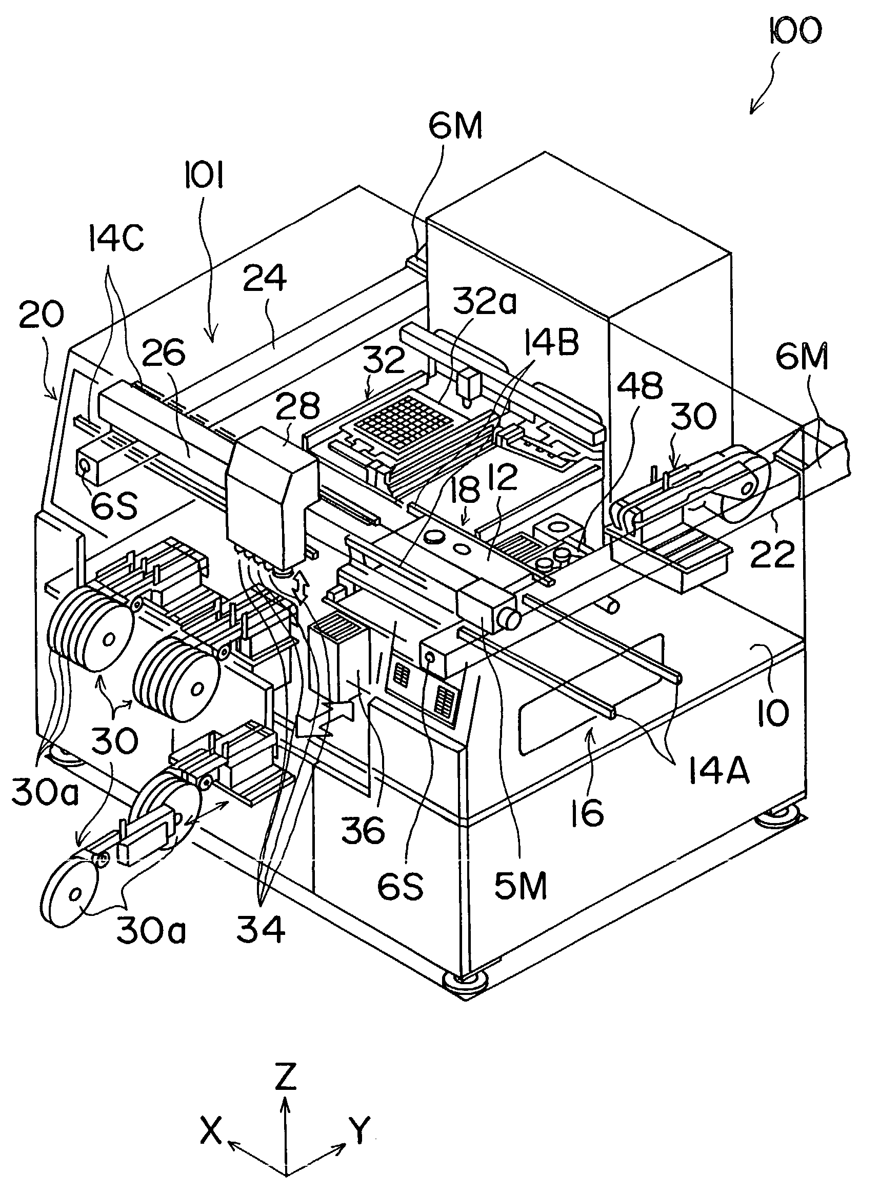
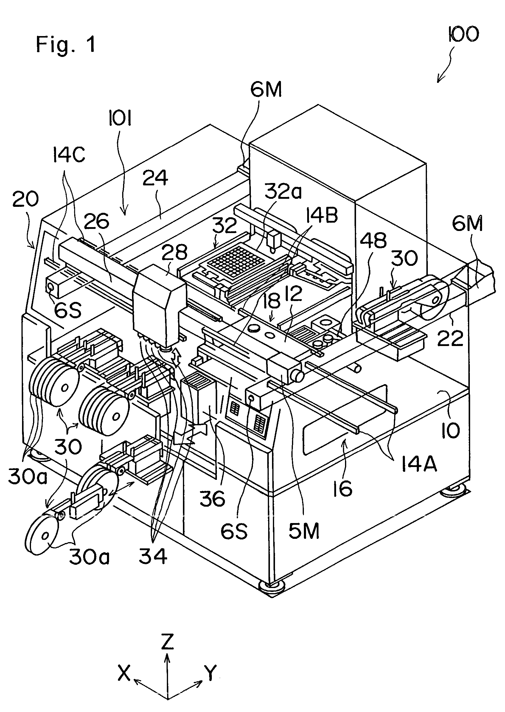
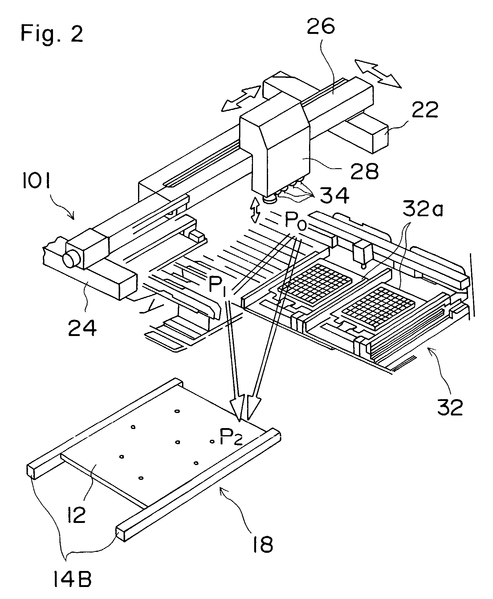
[0089]FIG. 1 is a perspective view showing an electronic component mounting apparatus incorporating a positioning control device according to the first embodiment of the present embodiment, and FIG. 2 is a perspective view showing a transfer head included therein. Although in the first embodiment, there is shown one example in which the positioning control method is applied to an electronic component mounting apparatus, the present invention is not limited to this example. The present invention may be applied, for example, to an assembly device for performing assembly with use of a transfer head that holds and transf...

Example

[0173]In the positioning control device in the second embodiment shown in FIGS. 24A and 24B, component members having the same structure as the positioning control device in the first embodiment shown in FIGS. 4A and 4B are designated by the same reference numerals. Description thereof, therefore, will be omitted here. In the positioning control device of the second embodiment, a conversion table 7 that defines a relationship between a travel amount and a moving time is connected to a positioning controller 2 in a manner enabling input / output. The conversion table 7 facilitates driving of transfer head 28, and enables driving with an arbitrary velocity change pattern such as a sigmoid driving type as shown in FIG. 25, thereby implementing slow rising and falling, resulting in implementation of positioning with low vibration and noise.

[0174]The conversion table 7 is used, as shown in FIGS. 24A and 24B, for setting a velocity change pattern from driving start of the transfer head 28 t...


PUM


Abstract

There are provided a positioning control method and a positioning control device, which enables high speed positioning with low power consumption without repeating two or more acceleration and deceleration operations during travel from an original position to a target position. There is also provided an electronic component mounting apparatus, which enables high speed positioning with low power consumption and enables mounting of electronic components in a short period of time. When a movable body is moved from the original position to the target position, there is set an operational passing position for avoiding a passing avoidance region, and driving of a drive unit having a smaller travel distance from the original position to a coordinate of the operational passing position is started later than driving start timing of a drive unit having a longer travel distance, from the original position to another coordinate of the operational passing position, by a specified period of time.

Description

[0001]This application is a National Stage application of PCT / JP01 / 00214, filed Jan. 16, 2001.TECHNICAL FIELD[0002]The present invention relates to a positioning control method, a positioning control device, and an electronic component mounting apparatus using the same. More specifically, the present invention relates to a positioning control technique suitably applied to, for example, a case of controlling high speed positioning of a movable body with low power consumption while avoiding an impassable area with use of a plurality of actuators.BACKGROUND ART[0003]In an electronic component mounting apparatus, for example, there are driven a plurality of actuators 81 and 82 such as servomotors as shown in FIG. 32, and there is used a positioning control device 80 for controlling a position of a transfer head 85, that is an example of a movable body, with use of a ball screw and the like to move the transfer head 85 from an original position to an arbitrary target position. Here, from...

Claims


Application Information

Patent Timeline
IPC IPC(8): G05B11/32B25J9/16G05B19/19G05B19/4061G05B19/416H05K13/08
CPCB25J9/1651B25J9/1666G05B19/19G05B19/4061H05K13/08G05B19/416G05B2219/40293G05B2219/43056G05B2219/43093G05B2219/45029H05K13/0406H05K13/0885
Inventor TANAKA, YOICHIKUROKAWA, TAKAHIROMATSUO, SEIICHI
Owner PANASONIC CORP
Why Eureka
Try Eureka