Cutting head mounting and support ring system

Active Publication Date: 2007-09-18
URSCHEL LAB
View PDF11 Cites 19 Cited by
  • Summary
  • Abstract
  • Description
  • Claims
  • Application Information

AI Technical Summary

Benefits of technology

[0015]The features of the interlocking joint arrangement of the invention reduce the potential for the tilting or lifting of the cutting head relative to the support ring during slicing operations mounting ring. Furthermore, the interlocking joint arrangement of the invention increases the efficiency of mounting a mounting ring to a support ring, and as a result, the process for removing or mounting a cutting head to a slicing machine is rendered less time consuming. It will also be understood that the interlocking joint arrangement of t

Problems solved by technology

Removal of the cutting head, or replacement or adjustment of the slicing blades is typically a time consuming procedure and thereby reduces production efficiency.
In this particular coupling arrangement, it has been observed that the pins of the cutting head may deform or the locating holes may elongate on the support ring over time, thereby rendering it difficult to properly position the cutting head on the support ring after repeated usage.
In the known coupling arrangements, it has been observed that the cutting he

Method used


Image

  • Cutting head mounting and support ring system
  • Cutting head mounting and support ring system
  • Cutting head mounting and support ring system

Examples


Example

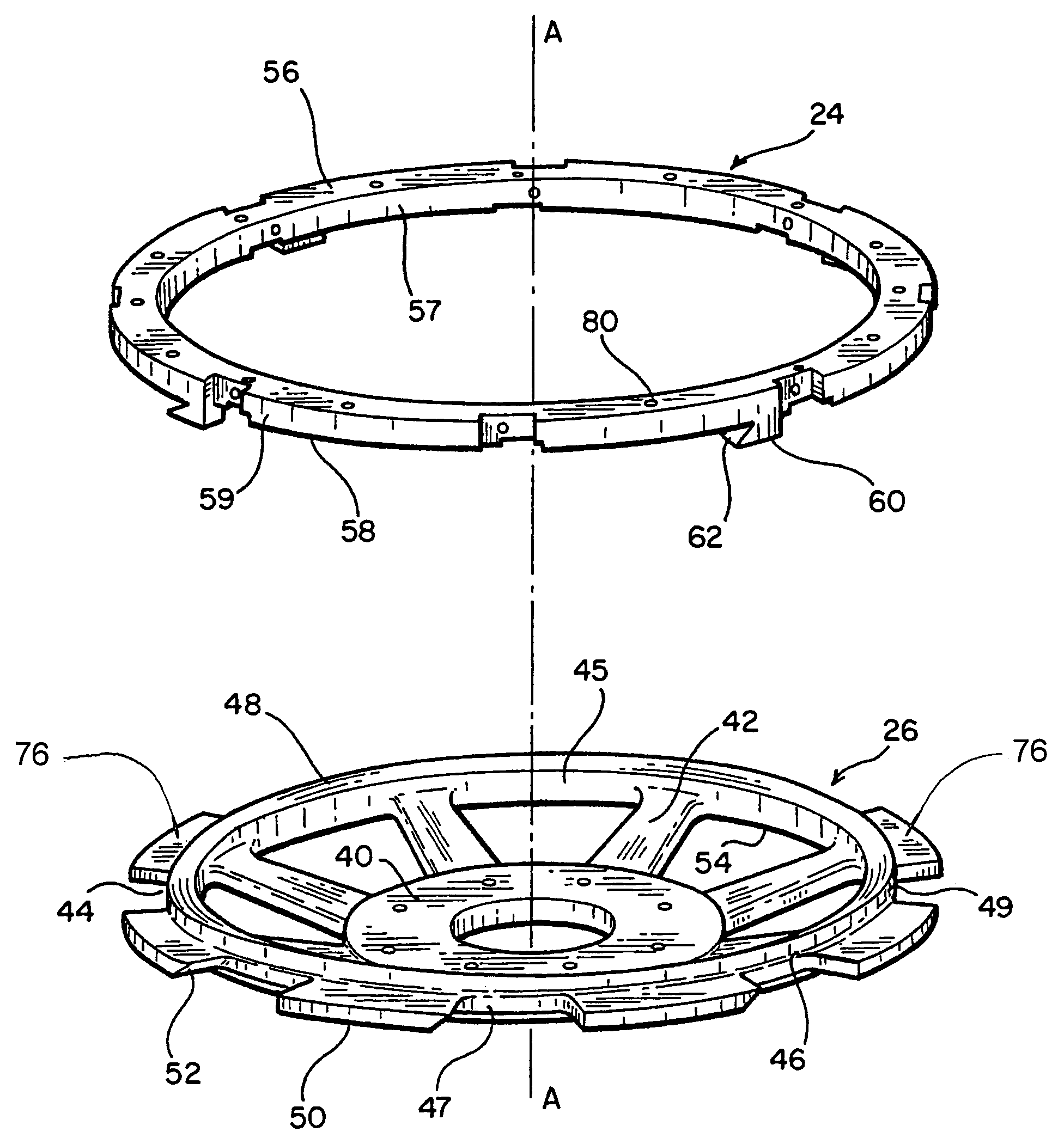
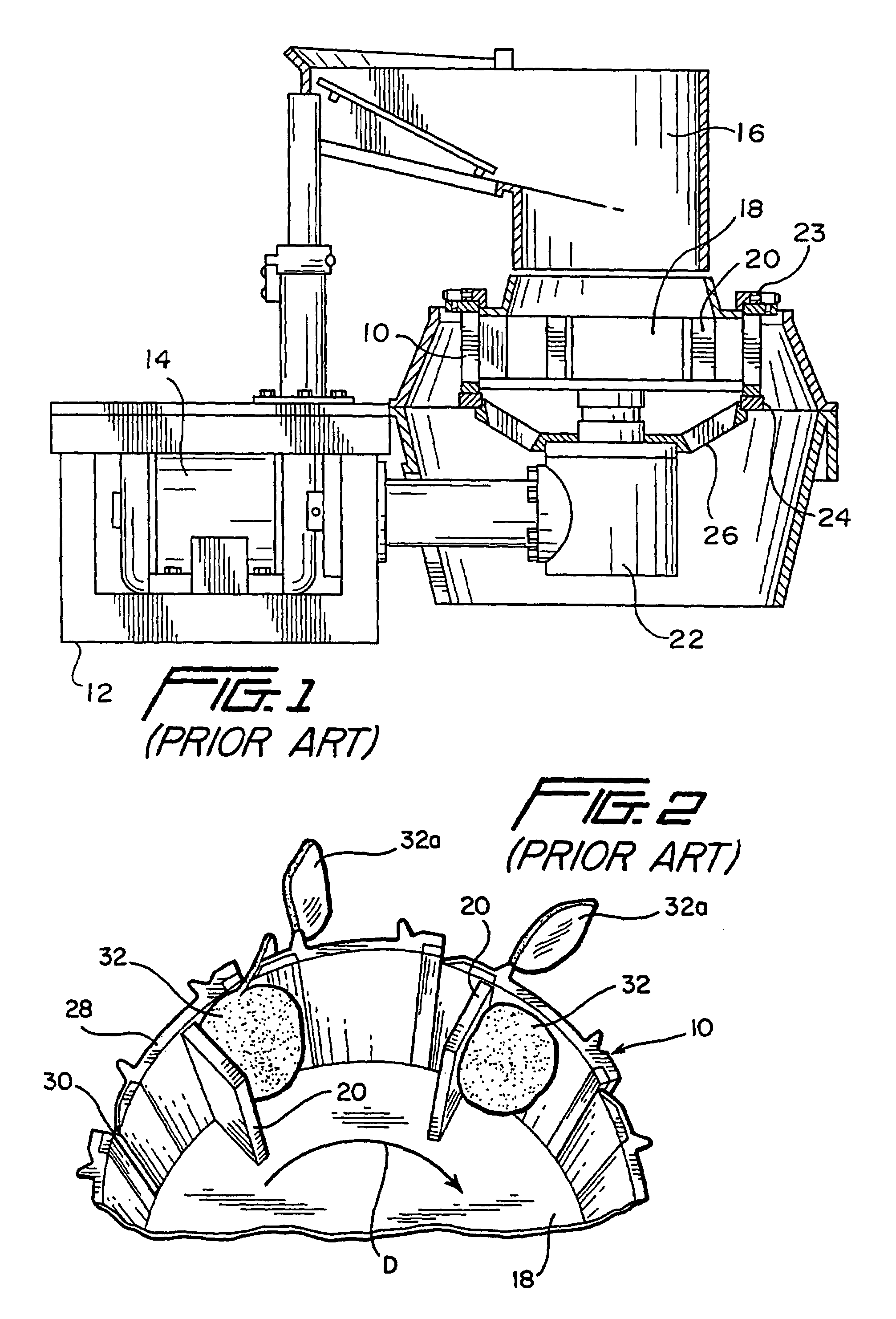
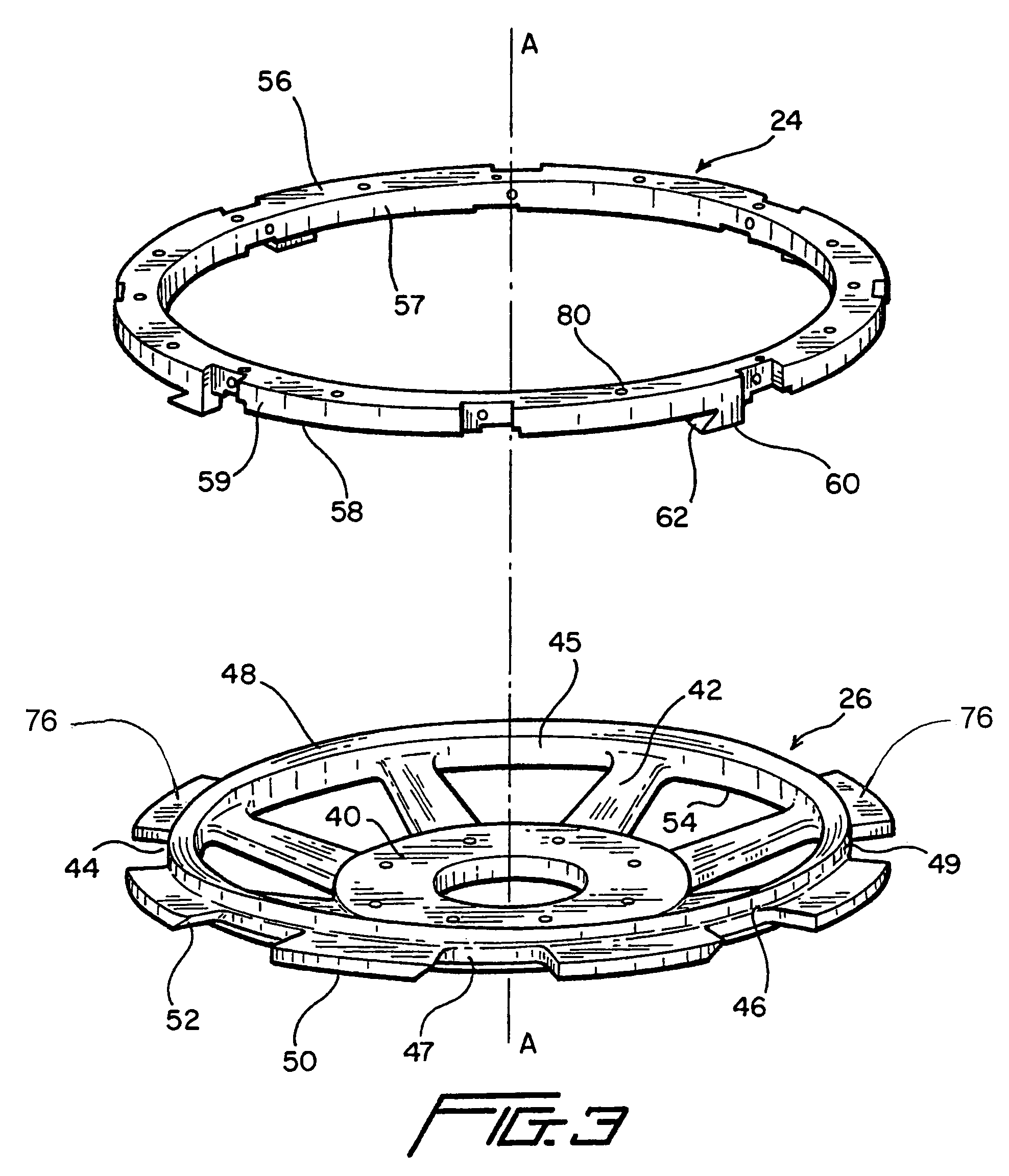
[0021]With reference now to the drawings, FIG. 1 shows a cutting head 10 mounted on a known slicing machine as is well known in the art and as is further described in U.S. Pat. No. 5,694,824, the entirety of which is incorporated herein by reference. The known slicing machine includes a main frame 12 upon which is mounted a drive motor 14 and a food product hopper 16. The motor 14 rotates an impeller 18 via gear box 22 such that food products dropped into the impeller are directed radially outwardly via centrifugal forces and caused to rotate by contact with the impeller blades 20 of the impeller 18. The cutting head 10 includes an upper annular ring 23 mounted on an upper side thereof and is fixedly mounted to a mounting ring 24 on a lower side thereof, which in turn is mounted on a support ring 26. The cutting head 10 is secured to the mounting ring 24, for example by fasteners, to removably attach the cutting head to the mounting ring 24. The mounting ring 24 is secured to the su...


PUM

PropertyMeasurementUnit
Angleaaaaaaaaaa
Diameteraaaaaaaaaa
Surfaceaaaaaaaaaa

Abstract

A cutting head mounting and supporting ring assembly having an interlocking joint arrangement for mounting the cutting head on a food slicing machine. The ring assembly includes a support ring having a plurality of circumferentially spaced, radially extending flange segments having a flange end portion inclined relative to the axis thereof, and a mounting ring having a plurality of circumferentially spaced axially extending protrusions having a protrusion end portion inclined relative to the axis thereof. The flange and protrusion surfaces of the flange segments and the protrusions are complementary shaped and arranged to mutually engage face-to-face to define scarf type joint connections when they are interdigited.

Description

[0001]This application claims the benefit of provisional application No. 60 / 466,403 filed Apr. 30, 2003.BACKGROUND OF THE INVENTION[0002]1. Field of the Invention[0003]The present invention relates to a cutting head mounting and support ring system for securing a cutting head to a food slicing machine.[0004]2. Discussion of Related Art[0005]Slicing machines for cutting food products, such as vegetables, nuts, and fruit, are well known in the art. A known apparatus is described in U.S. Pat. No. 5,694,824 and comprises a main frame, a drive motor, a stationary annular cutting head fixedly attached to the main frame and having a series of circumferentially spaced cutter support segments each with a slicing blade mounted thereon, and a rotatable impeller surrounded by the cutting head and connected to a drive motor for rotation within the cutting head. The cutting head and the impeller are configured so that the impeller directs a food product outwardly against the slicing blades when t...

Claims


Application Information

Patent Timeline
IPC IPC(8): B26D7/26B26D1/36
CPCB26D1/03B26D7/0691Y10T403/7009B26D7/2614Y10T83/9372Y10T83/217Y10T83/6473Y10T83/9464
Inventor KING, DANIEL W.JACKO, MICHAEL S.ARRASMITH, PAUL
Owner URSCHEL LAB
Why Eureka
Try Eureka