AI technical title is built by Patsnap AI team. It summarizes the technical point description of the patent document.
a technology for extending the cargo bed and the extender, which is applied in the direction of roofs, transportation items, manufacturing tools, etc., can solve the problems of reducing the service life of the extender, the load falling out of the back of the truck, and the undesirable configuration of the storage bed, so as to reduce the movement and vibration of the extender, increase the strength and rigidity of the extender, and reduce the effect of movemen
Inactive Publication Date: 2006-06-20
LUND MOTION PRODS
View PDF74 Cites 43 Cited by
Summary
Abstract
Description
Claims
Application Information
AI Technical Summary
This helps you quickly interpret patents by identifying the three key elements:
Problems solved by technology
Method used
Benefits of technology
Benefits of technology
[0008]The extender may also comprise a first L-shaped section defining the first side wall and a first portion of the connecting wall and a second L-shaped section defining the second side wall and a second portion of the connecting wall. Advantageously, these L-shaped portions significantly increase the strength and rigidity of the extender, enhancing its ability to withstand bumping by heavy cargo, such as motorcycles, as well as external impact.
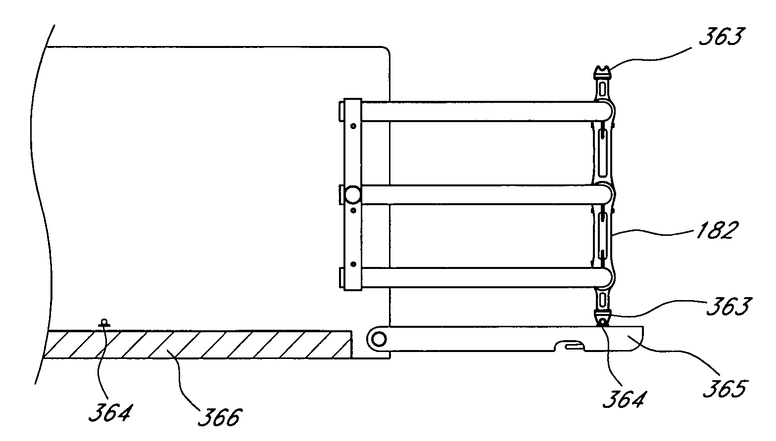
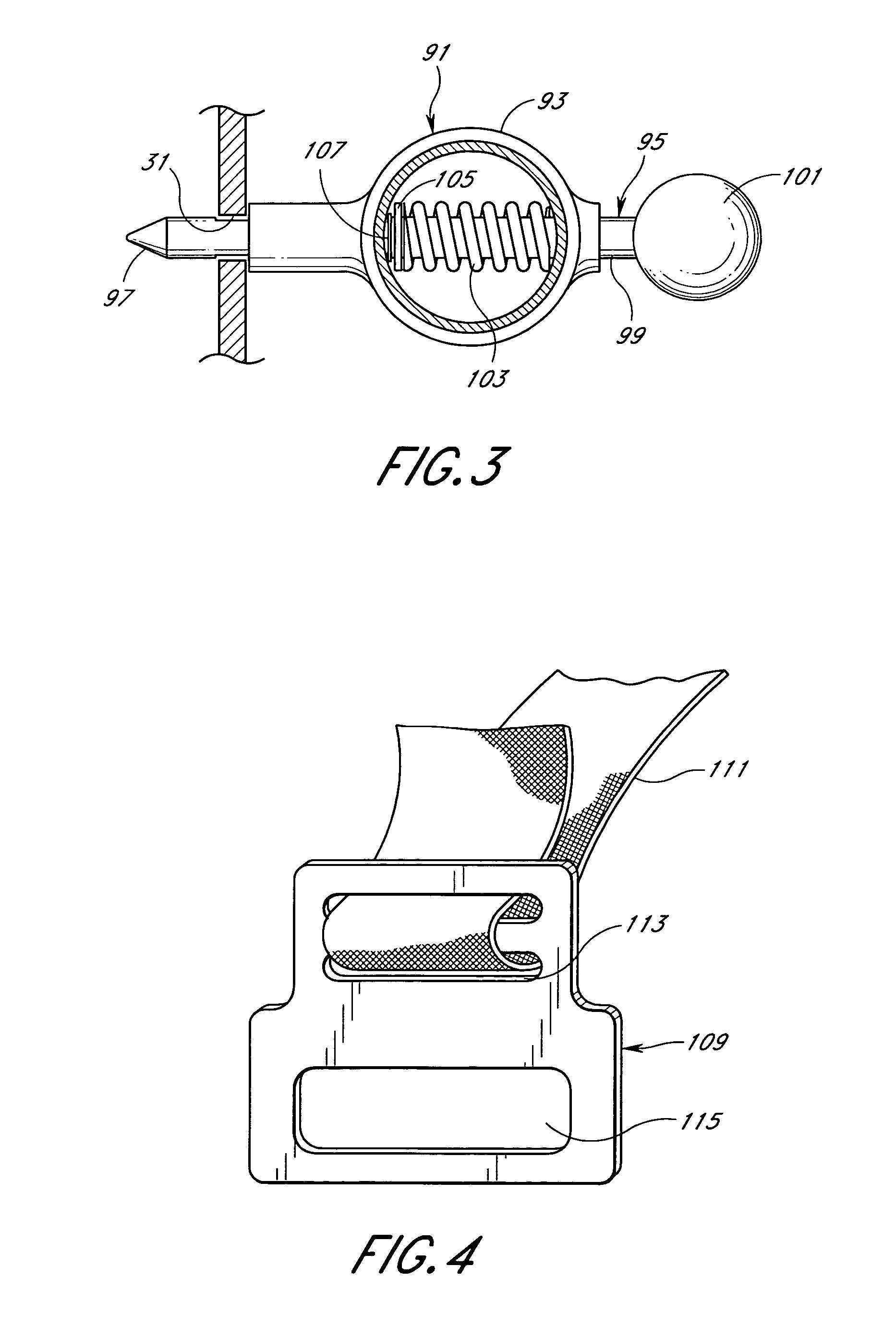
[0009]Yet another important aspect of the invention is at least one buckle secured to one of the walls sized and shaped to be releasably locked to the latch of the vehicle tailgate. Significantly, the buckle provides a supplemental attachment point which minimizes movement and vibration of the extender while driving and is quickly releasable by using the vehicle tailgate's own opening mechanism.
[0016]Another aspect of the invention is a method for an individual to mount a vehicle bed extender on a vehicle without tools including: ( ) aligning a first mount fixed with respect to the extender with a first space defined by the first station and aligning a second mount fixed with respect to the extender with a second space defined by the second station; ( ) moving the bed extender such that the first mount moves radially through the first space with respect to an axis defined by the first station and the second station and the second mount moves radially with respect to the axis through the second space; and ( ) pivoting the extender about the axis so that the first mount cooperates with the first station and the second mount cooperates with the second station to prevent radial movement of the first mount with respect to the axis and the second mount with respect to the axis.
[0019]Yet another aspect of the invention is the truck bed extender for use with a vehicle having an open storage bed having a rear end, a first standing side panel to one side of the bed, a second upstanding side panel to an opposite side of the bed and a tailgate, a first mounting station fixed with respect to the first upstanding panel defining a first station surface and a second mounting station fixed with respect to the second upstanding panel defining a second station surface. The extender includes a first sidewall, a second sidewall, a connecting wall extending between the first sidewall and the second sidewall, a first mount secured to the first sidewall, and a second mount secured to the second sidewall. The first sidewall of the second sidewall and the connecting wall cooperate to form a generally u-shaped frame. The first mount defines a first mount surface and the second mount defines a second mount surface. The first station surface and the first mount surface, and the second station surface and the first mount surface cooperate to secure the apparatus to the vehicle so that the connecting wall is in an upright position over the tailgate rearward of the rear end of the bed. The tailgate defines a latch to secure the tailgate to at least one of the first upstanding panel and the second upstanding panel. The truck bed extender further includes at least one interlock member secured to one of the walls sized and shaped to be releasably captured by the latch of the tailgate. Desirably, the interlock member comprises a buckle or a cylindrical interlock portion rigidly secured to the connecting wall. Significantly, this stabilizes the tailgate against movement when the vehicle strikes an object, such as a speed bump.
Problems solved by technology
Unfortunately, often the storage bed is of an undesirable configuration for the load being transported.
Unfortunately, this raises the risk that the load will fall out of the back of the truck, or that the load will need to be tied down, taking additional time.
Method used
Image
Click on the blue label to locate the original text in one second.
Reading with bidirectional positioning of images and text.
Examples
Embodiment Construction
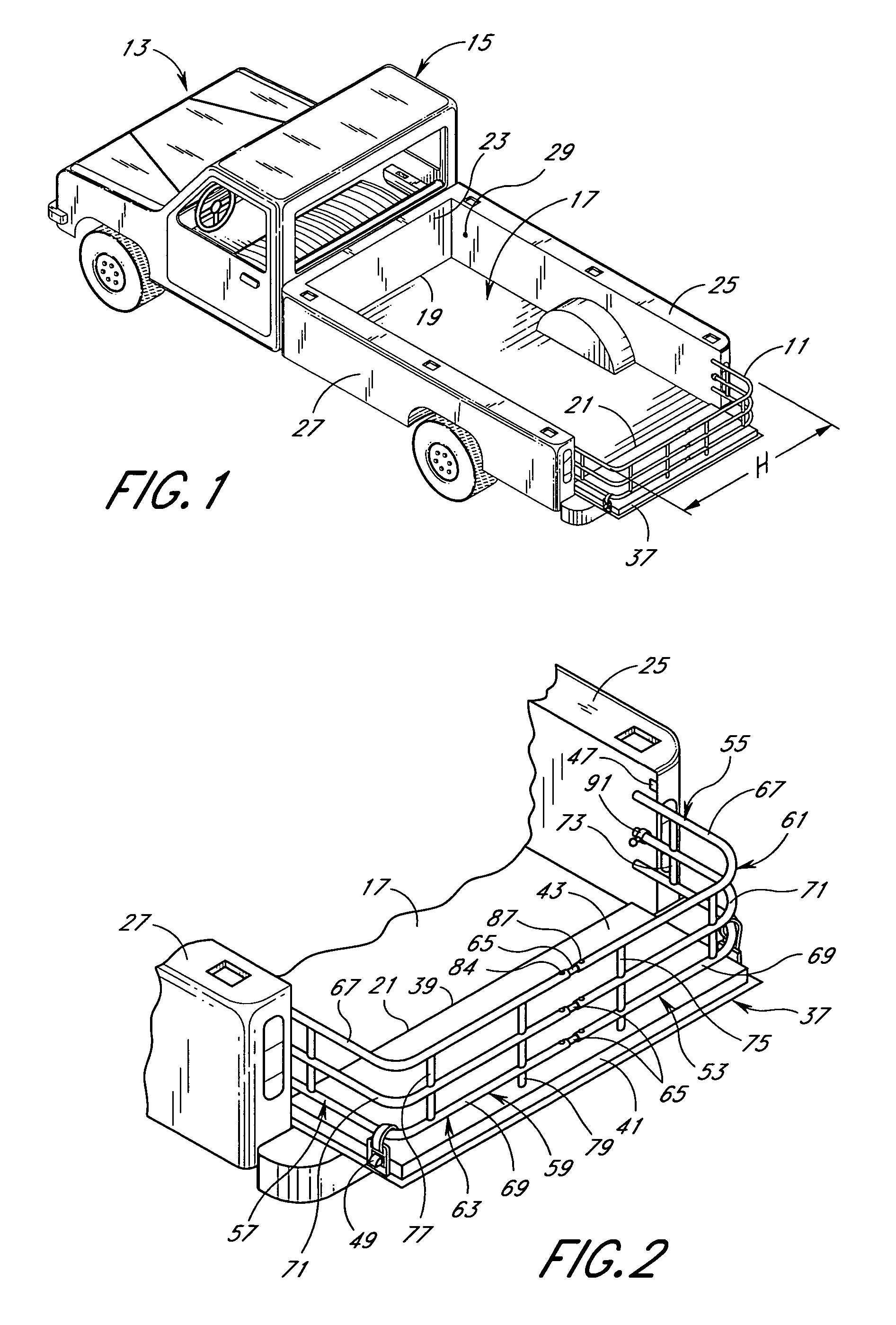
[0053]The preferred embodiment of a multi-purpose apparatus or truck bed extender 11 will now be described with reference to the FIGS. Referring to FIGS. 1 and 2, the truck bed extender 11 is shown mounted on a truck 13 having a cab 15 to the rear of which is a storage bed 17. The storage bed 17 has a front end 19 and a rear end 21. The front end 19 of the storage bed is defined by a front upstanding panel 23 and the sides of the storage bed are defined by a first side upstanding panel 25 and a second side upstanding panel 27. The first side upstanding panel 25 defines a first forward mounting station or aperture 29 and a first rearward mounting station or aperture 31 (FIG. 3), the purpose and location of which will be discussed in greater detail below. Likewise, the second side upstanding panel 27 defines a second forward aperture (not shown) and a second rearward aperture (not shown).
[0054]At the rear end 21 of the storage bed 17 is a tailgate 37. The tailgate has a hinge end 39 a...
PUM
Abstract
An improved truck bed extender particularly adapted for ease of installation and removal. When not being used to extend the truck bed, the extender is advantageously adapted to quickly and easily create a secondary storage area. In one embodiment, the extender includes a first side wall, a second side wall, a connecting wall, a first mount and a second mount. The connecting wall extends between the first side wall and the second side wall, and cooperates with the first side wall and second side wall to form a generally U-shape frame. The first mount is secured to the first side wall and includes a first interlocking member. The second mount is secured to the second side wall and comprises a second interlocking member. The first interlocking member and the first mounting station on the vehicle and the second interlocking member and the second mounting station on the vehicle cooperate to secure the truck bed extender to the vehicle so that the extender is rotatable about an axis between a first and a second position. In the first position, the connecting wall is in an upright position over the tailgate beyond the rear end of the bed. In the second position, the connecting wall is in an upright position spaced forward from the rear end of the bed and the tailgate.
Description
[0001]This application is a continuation of prior U.S. patent application Ser. No. 10 / 171,456, filed Jun. 11, 2002, which issued as U.S. Pat. No. 6,805,392, which is a continuation of prior U.S. patent application Ser. No. 09 / 524,332, filed Mar. 13, 2000, which issued as U.S. Pat. No. 6,402,215, which is a continuation of prior U.S. patent application Ser. No. 09 / 347,472, filed Jul. 2, 1999 and abandoned, which claims the benefit of prior U.S. Provisional Patent Application Ser. No. 60 / 091,623, filed Jul. 2, 1998, and is a continuation-in-part of prior U.S. patent application Ser. No. 09 / 022,951, filed Feb. 12, 1998, and abandoned, which claims the benefit of prior U.S. Provisional Patent Application Ser. No. 60 / 063,784, filed Oct. 31, 1997, and is a continuation-in-part of prior U.S. patent application Ser. No. 08 / 924,230, filed Sep. 5, 1997, which issued as U.S. Pat. No. 6,113,173 and which is a continuation of prior U.S. patent application Ser. No. 08 / 651,921, filed on May. 21, 1...
Claims
Application Information
Patent Timeline
Application Date:The date an application was filed.
Publication Date:The date a patent or application was officially published.
First Publication Date:The earliest publication date of a patent with the same application number.
Issue Date:Publication date of the patent grant document.
PCT Entry Date:The Entry date of PCT National Phase.
Estimated Expiry Date:The statutory expiry date of a patent right according to the Patent Law, and it is the longest term of protection that the patent right can achieve without the termination of the patent right due to other reasons(Term extension factor has been taken into account ).
Invalid Date:Actual expiry date is based on effective date or publication date of legal transaction data of invalid patent.

