Cooling fan

a cooling fan and fan body technology, applied in the direction of machines/engines, stators, liquid fuel engines, etc., can solve the problems of affecting the airflow affecting the cooling effect of the blade, and accumulating heat produced by electric currents, etc., to achieve the effect of enhancing the cooling performance of the blade, reducing height, and increasing the air introduction area

Inactive Publication Date: 2006-06-20
DELTA ELECTRONICS INC
View PDF16 Cites 37 Cited by
  • Summary
  • Abstract
  • Description
  • Claims
  • Application Information

AI Technical Summary

Benefits of technology

[0006]A primary objective of the present invention is to provide a cooling fan for use in a decreasingly sized computer, wherein the cooling fan is adapted to have increased air introduction area to enhance cooling performance thereof.
[0007]Another objective of the invention is to provide a cooling fan, wherein a frame of the cooling fan is formed with a reduced height so as to increase air introduction area and airflow effect for the cooling fan.
[0008]A further objective of the invention is to provide a cooling fan, for allowing air to be smoothly introduced into operative part of a computer, so as to conduct good heat dissipation and help prolong lifetime of the computer.
[0009]To achieve the above and other objectives, the present invention proposes a cooling fan including a plurality of blades; and a frame for receiving the blades therein, wherein the frame has a reduced height for exposing the blades to outside of the frame so as to allow air to enter into the frame via a top portion and a peripheral portion of the blades to thereby improve air introduction and heat dissipating efficiency of the cooling fan.
[0010]The above cooling fan may further include a cover mounted on a top surface of the frame. The cover serves as a protective shield to prevent an operator from being in contact with or injured by the blades during maintaining or repairing a computer. The cover may be formed with a plurality of openings for allowing air to enter into the frame through the openings, and thereby helps enhance air intake and working efficiency of the cooling fan.

Problems solved by technology

For example, a central processing unit (CPU) of computer may be formed with chips operating at a high speed up to 1–2 GHz, and such high-speed operation would lead to accumulation of heat produced from electric currents by effect of resistance in the CPU.
As such, if a block is situated closely in front of the air inlet, it would impede movement of air and adversely affect airflow effect for the blades 103.
Moreover, in response to profile miniaturization of electronic products, a computer is provided with limited internal space for receiving a reduced-sized cooling fan connected to heat sinks.
As a result, the cooling fan may be located very close to a housing of the computer, which reduces air introduction area and space / distance for generating airflow effect, and thereby leads to poor heat dissipation for the computer.
Therefore, the problem to be solved herein is to provide a cooling fan with enhanced cooling effect for use in a limited-sized computer.

Method used


Image

  • Cooling fan
  • Cooling fan
  • Cooling fan

Examples


Embodiment Construction

[0022]The following description is made with reference to FIGS. 2–7 for depicting preferred embodiments of a cooling fan provided in the present invention.

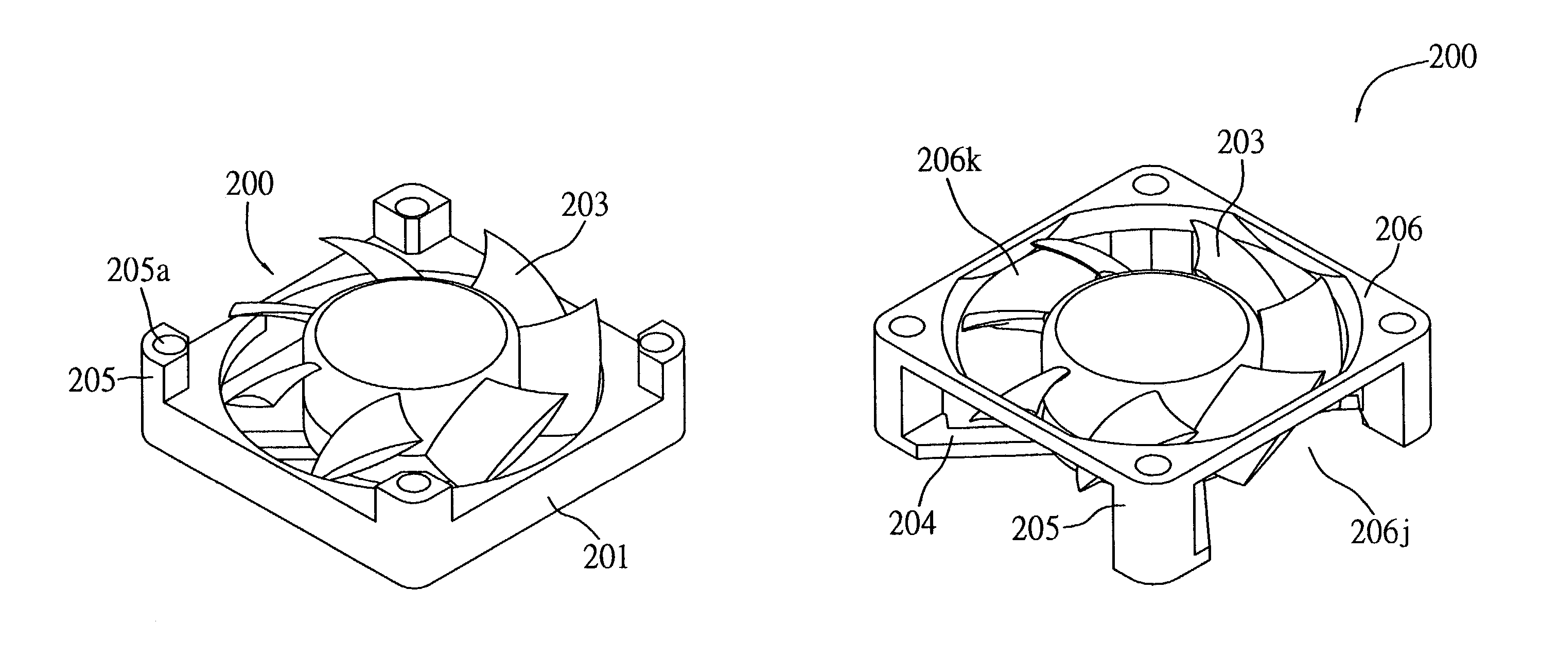
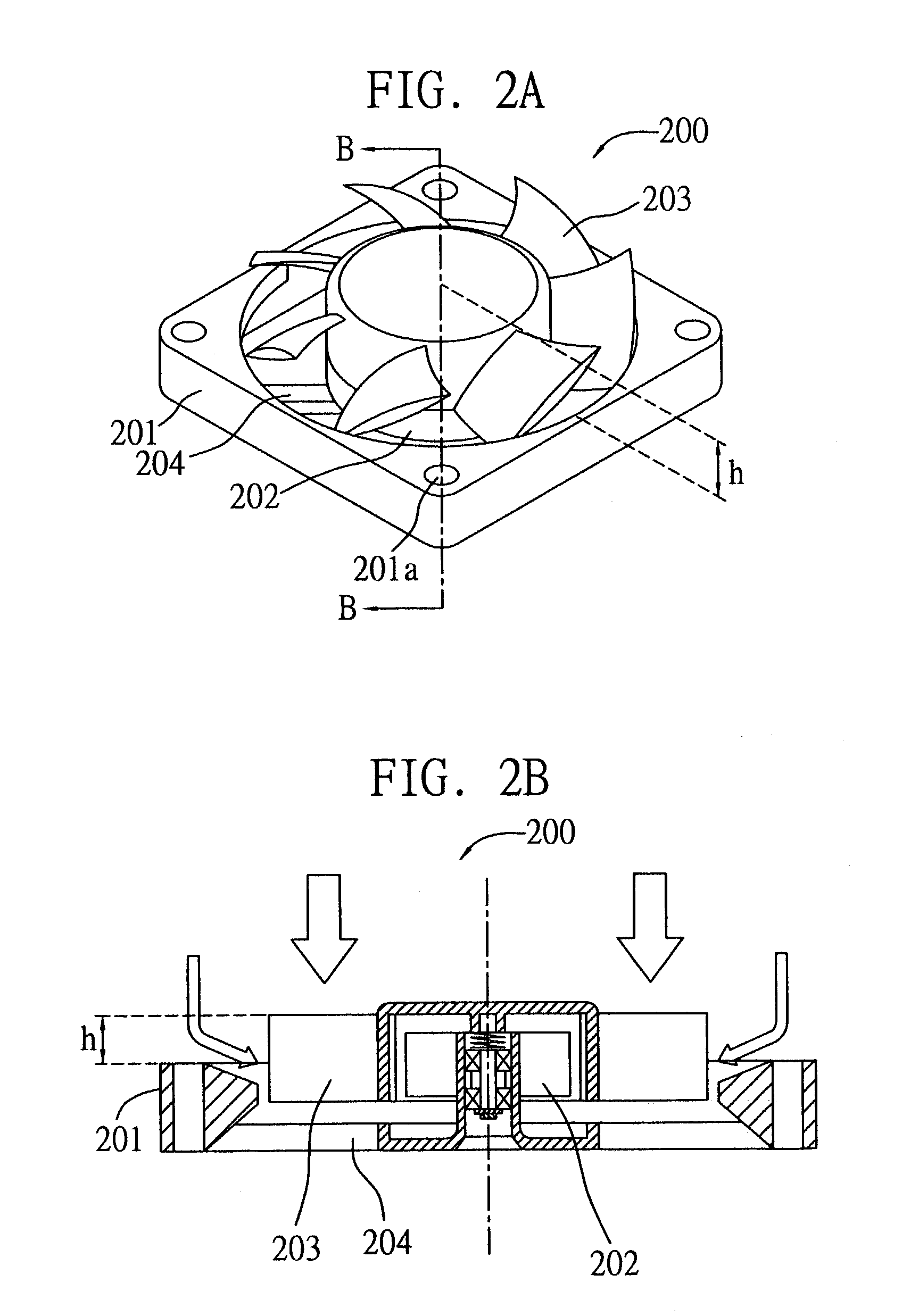
[0023]FIGS. 2A and 2B illustrate a cooling fan 200 according to a first embodiment of the invention. As shown in the drawings, the cooling fan 200 includes a plurality of blades 203 connected to and driven by a driving means such as a motor 202 to rotate and thereby suck in or exhaust air to create airflow effect; and a frame 201 formed with a reduced height to increase air introduction area and receiving the blades 203, wherein a plurality of through holes 201a are peripherally formed on the frame 201 and can be engaged with mounting screws (not shown) for connecting the cooling fan 200 to a heat sink (not shown) conventionally used in a computer.

[0024]The frame 201 is reduced in height by a distance h from the top of the cooling fan 200 in a manner as to increase contact area between the blades 203 received within the frame 201 ...


PUM


Abstract

A cooling fan with high heat-dissipating performance includes a plurality of blades; and a frame for receiving the blades therein, wherein the frame has a reduced height for exposing the blades to outside of the frame so as to allow air to enter into the frame via a top portion and a peripheral portion of the blades to improve air introduction and heat dissipating efficiency of the cooling fan. A cover may be mounted to a top surface of the frame, and formed with a plurality of openings for allowing air to enter into the frame through the openings; such an arrangement cam effectively enhance air intake and working efficiency of the cooling fan.

Description

FIELD OF THE INVENTION[0001]The present invention relates to cooling fans, and more particularly, to a cooling fan for dissipating heat produced by internal elements of a computer, wherein a frame of the cooling fan for receiving blades is formed with a reduced height to increase air introduction area and thus to enhance working efficiency of the cooling fan.BACKGROUND OF THE INVENTION[0002]As electronic and information industries prosperously develop, various kinds of electronic products with different appearances and functions are introduced into the market. For example, a central processing unit (CPU) of computer may be formed with chips operating at a high speed up to 1–2 GHz, and such high-speed operation would lead to accumulation of heat produced from electric currents by effect of resistance in the CPU. Therefore, the computer is mostly mounted with a heat-dissipating device, so as to confine operation of the CPU within a certain range of temperature and to prevent the chips...

Claims


Application Information

Patent Timeline
Patent Type & Authority Patents(United States)
IPC IPC(8): F04D29/52F04D25/06
CPCF04D29/526F04D25/0613
Inventor HUANG, WEN-SHILIN, KUO-CHENGTAN, LI-KUANGLEI, TSUNG-YULIU, WEN-HA
Owner DELTA ELECTRONICS INC
Why Eureka
Try Eureka