Exchange coupling film, magnetic detecting element using the exchange coupling film, and method of making same

a technology of exchange coupling and magnetic detecting elements, applied in the field of exchange coupling films, magnetic detecting elements using exchange coupling films, and making same, can solve the problems of deteriorating communication reliability and increasing the degree of asymmetry of output signal waveforms, and achieves the effects of improving communication reliability, reducing the degree of asymmetry of output signal waveforms, and high resistance to damag

Inactive Publication Date: 2006-06-20
ALPS ALPINE CO LTD
View PDF18 Cites 12 Cited by
  • Summary
  • Abstract
  • Description
  • Claims
  • Application Information

AI Technical Summary

Benefits of technology

[0060]The magnetic detecting element of the present invention uses the exchange coupling film comprising the pinned magnetic layer and the antiferromagnetic layer containing a Cr element with a concentration gradient in the thickness direction, so that the exchange coupling magnetic field produced between the antiferromagnetic layer and the pinned magnetic layer can be increased.
[0061]The magnetic detecting element of the present invention may use the exchange coupling film comprising the pinned magnetic layer and the antiferromagnetic layer both of which contain a Cr element with a concentration gradient in the thickness direction, so that the exchange coupling magnetic field produced between the antiferromagnetic layer and the pinned magnetic layer can be increased.
[0062]The magnetic detecting element of the present invention may use the exchange coupling film comprising the antiferromagnetic layer and the pinned magnetic layer containing a Cr element with a concentration

Problems solved by technology

Therefore, it is difficult to maintain a constant crossing angle between the magnetization directions of the pinned magnetic layer 103 and the free magnetic layer 105, thereby causing the problem of increasing a degree of asymmetry

Method used


Image

  • Exchange coupling film, magnetic detecting element using the exchange coupling film, and method of making same
  • Exchange coupling film, magnetic detecting element using the exchange coupling film, and method of making same
  • Exchange coupling film, magnetic detecting element using the exchange coupling film, and method of making same

Examples


examples

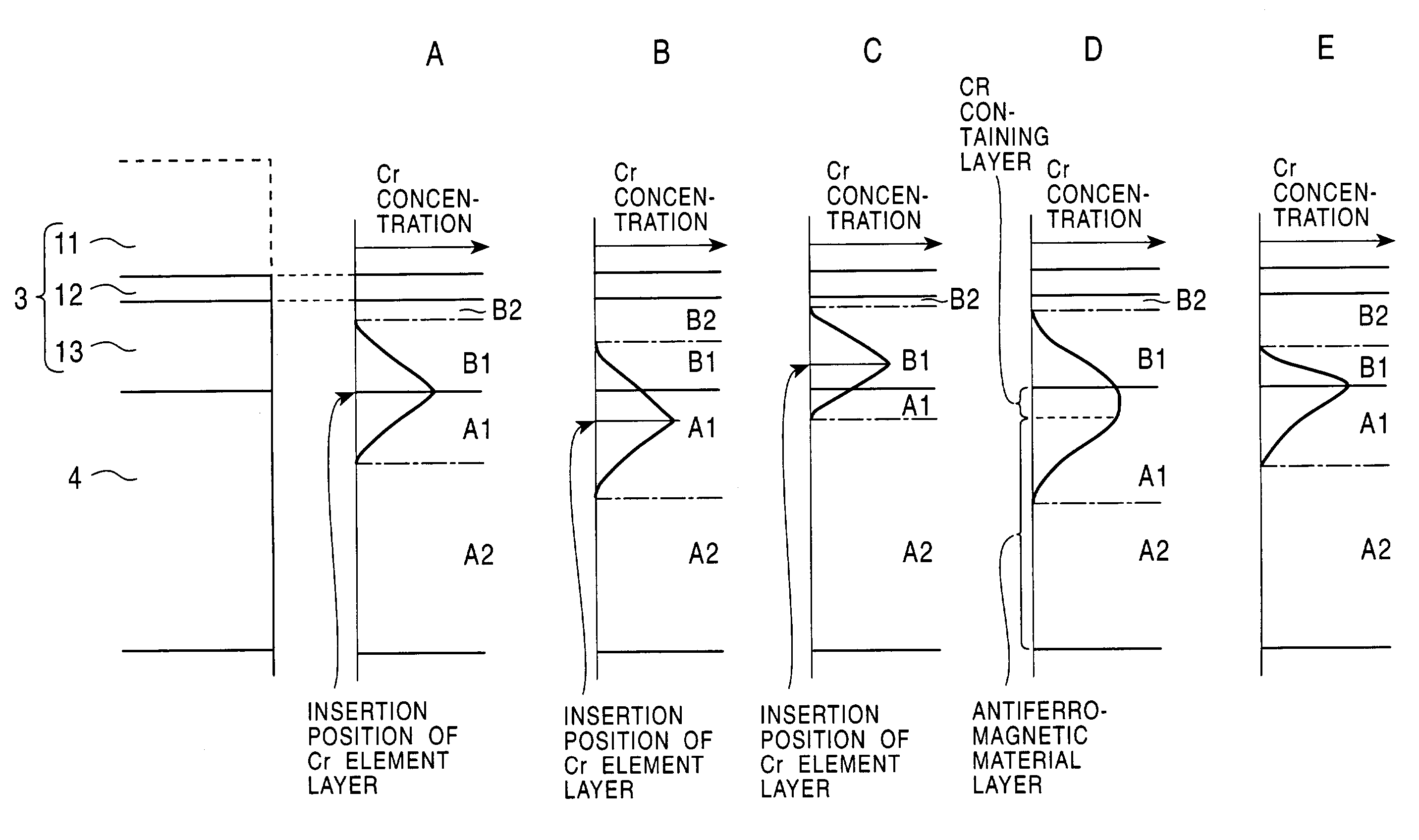
[0292]Studies were made of the thickness and formation position of the Cr element layer 50 formed in the method of producing the exchange coupling film shown in each of FIGS. 5, 6 and 7. In the description below, a Cr element layer means a thin film layer comprising only Cr.

[0293]In a graph of FIG. 12, a solid line of Δ shows changes in the exchange coupling magnetic field of an exchange coupling film (corresponding to the exchange coupling film shown in FIG. 5) after heat treatment with changes in the thickness of a Cr element layer inserted into the interface between a pinned magnetic layer and an antiferromagnetic layer.

[0294]In experiments, a thin film laminate having the following film structure was used.

[0295]Thin film laminate: silicon substrate / alumina (1000 Å) / (Ni0.8Fe0.2)60Cr40 (55 Å) / Pt50Mn50 (160 Å) / Cr (X Å) / Co90Fe10 (16 Å) / Cu (40 Å) / Co90Fe10 (10 Å) / Ni80Fe20 (50 Å) / Ta (30 Å) Each of the films was formed as a solid film.

[0296]In the graph of FIG. 12, a solid line of ∘ sho...


PUM

PropertyMeasurementUnit
Lattice constantaaaaaaaaaa
Antiferromagnetismaaaaaaaaaa
Concentrationaaaaaaaaaa

Abstract

Each of an antiferromagnetic layer and a pinned magnetic layer has a region containing a Cr element, thereby increasing an exchange coupling magnetic field (Hex) produced between the antiferromagnetic layer and the pinned magnetic layer. Therefore, the exchange coupling magnetic field produced between the antiferromagnetic layer and the pinned magnetic layer can be increased, and a coupling magnetic field due to RKKY interaction can also be increased, thereby increasing a one-directional exchange bias magnetic field (Hex*) in the pinned magnetic layer as compared with a conventional exchange coupling film.

Description

BACKGROUND OF THE INVENTION[0001]1. Field of the Invention[0002]The present invention relates to an exchange coupling film which comprises an antiferromagnetic layer and a ferromagnetic layer and which produces an exchange coupling magnetic field (Hex) at the interface between the antiferromagnetic layer and the ferromagnetic layer to align a magnetization direction of the ferromagnetic layer in a predetermined direction, a method of producing the exchange coupling film, and a magnetic detecting element using the exchange coupling film. Particularly, the present invention relates to an exchange coupling film capable of improving an exchange coupling magnetic field (Hex), a method of producing the exchange coupling film, and a magnetic detecting element using the exchange coupling film.[0003]2. Description of the Related Art[0004]FIG. 17 is a partial sectional view of a structure of a conventional magnetic detecting element, as viewed from a side facing a recording medium.[0005]In FI...

Claims


Application Information

Patent Timeline
IPC IPC(8): G11B5/127G11B5/39G01R33/09H01F10/14H01F10/32H01F41/18H01L43/08H01L43/10H01L43/12
CPCB82Y10/00B82Y25/00G01R33/093H01F10/3268G11B5/3903G11B5/3932Y10T428/115H01F41/325Y10T428/1121Y10T428/32G11B2005/3996
Inventor IKARASHI, KAZUAKIHASEGAWA, NAOYA
Owner ALPS ALPINE CO LTD
Why Eureka
Try Eureka