Bias system and method

a bias system and bias technology, applied in amplifiers with semiconductor devices/discharge tubes, amplifier modifications to reduce non-linear distortion, gain control, etc., can solve problems such as non-linear region, crossover distortion in circuits that use devices operating

Active Publication Date: 2006-06-20
TEXAS INSTR INC
View PDF9 Cites 72 Cited by
  • Summary
  • Abstract
  • Description
  • Claims
  • Application Information

AI Technical Summary

Benefits of technology

[0006]Another aspect of the present invention is a method comprising monitoring an input signal, and modifying an amplifier bias based on the monitored input signal to provide a boost during a predetermined time period. The input signal can be amplified employing the modified bias. The boost to the bias can be turned on in the presence of an input signal, and can be discontinued after no input signal has been detected. The boost can be phase shifted from the input signal, for example the bias can be phase shifted by ninety degrees based on the input signal. Furthermore, the method can provide the maximum bias during the amplifier's crossover period.

Problems solved by technology

Crossover distortion occurs in circuits that use devices operating in a “push-pull” manner.
However, if the circuit is not designed to achieve a smooth crossover or transition from one device to another, then there can be a non-linear region of the transfer characteristics (e.g., when the output has a zero amplitude for a non-zero input).

Method used


Image

  • Bias system and method
  • Bias system and method
  • Bias system and method

Examples


Embodiment Construction

[0017]The present invention relates to systems and methods that boost the bias of a device based on an input signal to the device. The boost can be provided at and / or near zero crossing amplitudes or at another predetermined input signal amplitude range. The device may have a fixed bias, and the bias device can be connected in parallel with the fixed bias. Additionally, the bias boost can be phase shifted based on the input signal. The bias signal from the bias device can be shifted substantially ninety degrees from the input signal. The bias boost can be provided as a full-wave rectified current signal.

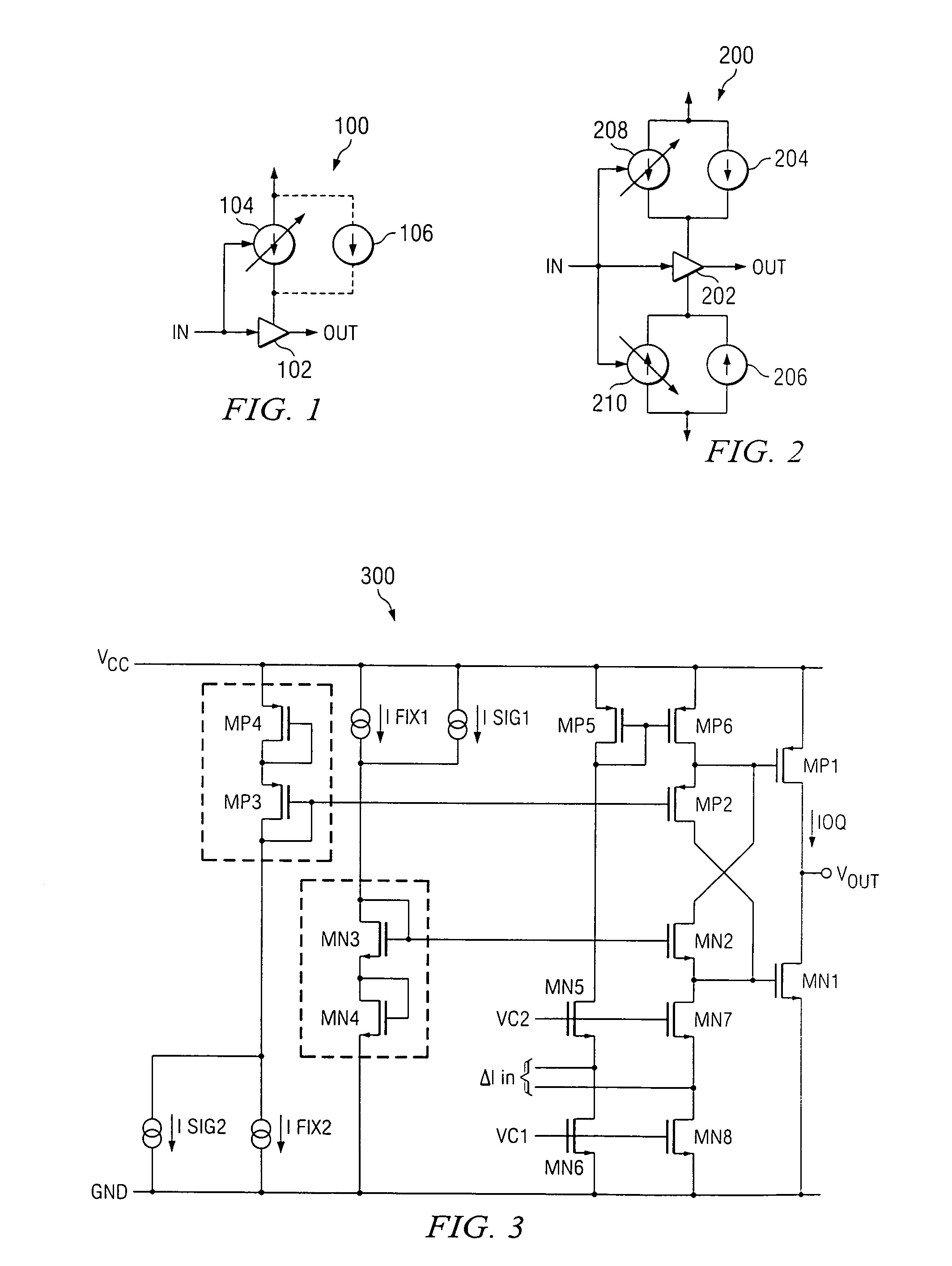
[0018]Referring to FIG. 1, there is illustrated a system 100 in accordance with an aspect of the present invention. The system 100 comprises a device 102 that provides an output signal (OUT) based on an input signal (IN). The device 102 has an associated bias device 104. Bias device 104 comprises a variable current source that modifies the bias to device 102 based on the input signal...


PUM


Abstract

A bias device that modifies the bias of a device based on an input signal to the device. The device may have a fixed bias, and the bias device can be connected in parallel with the fixed bias. The device can be an amplifier, such as a linear amplifier or a class AB amplifier. The bias device can be configured to provide maximum bias during the device's crossover time period.

Description

TECHNICAL FIELD[0001]The present invention is directed to biasing devices, and more particularly to a system and method for providing additional bias to a circuit during a predetermined time period.BACKGROUND OF THE INVENTION[0002]An ideal amplifier exhibits a linear transfer characteristic. For real amplifiers, biasing is a technique used to achieve linear operation. This can be achieved by biasing the circuit by applying a direct current (DC) voltage or current to select an operating point, or the quiescent point. The signal to be amplified is then superimposed on the DC bias. The bias point should be set high enough so that the amplifier does not enter a cut-off state while amplifying the signal, and yet low enough so that the amplifier does not saturate.[0003]Crossover distortion occurs in circuits that use devices operating in a “push-pull” manner. The devices are used in pairs and each device operates for only a half cycle of the input signal (e.g., class AB operation). Howeve...

Claims


Application Information

Patent Timeline
Patent Type & Authority Patents(United States)
IPC IPC(8): H03G3/20H03F1/02H03F1/32
CPCH03F1/0261H03F3/3022H03F1/3217
Inventor MACLEAN, KENNETH GEORGERAJASEKHAR, SURIBHOTLA VENKATABALDWIN, DAVID JOHNCORSI, MARCOHAGAN, TOBIN
Owner TEXAS INSTR INC
Why Eureka
Try Eureka