
Bad pixel correction while preserving features

a technology of features and pixel correction, applied in the field of image processing, can solve problems such as unsatisfactory smooth detail features of images

Inactive Publication Date: 2006-06-20
RE SECURED NETWORKS LLC +2
View PDF7 Cites 17 Cited by
  • Summary
  • Abstract
  • Description
  • Claims
  • Application Information

AI Technical Summary

Benefits of technology

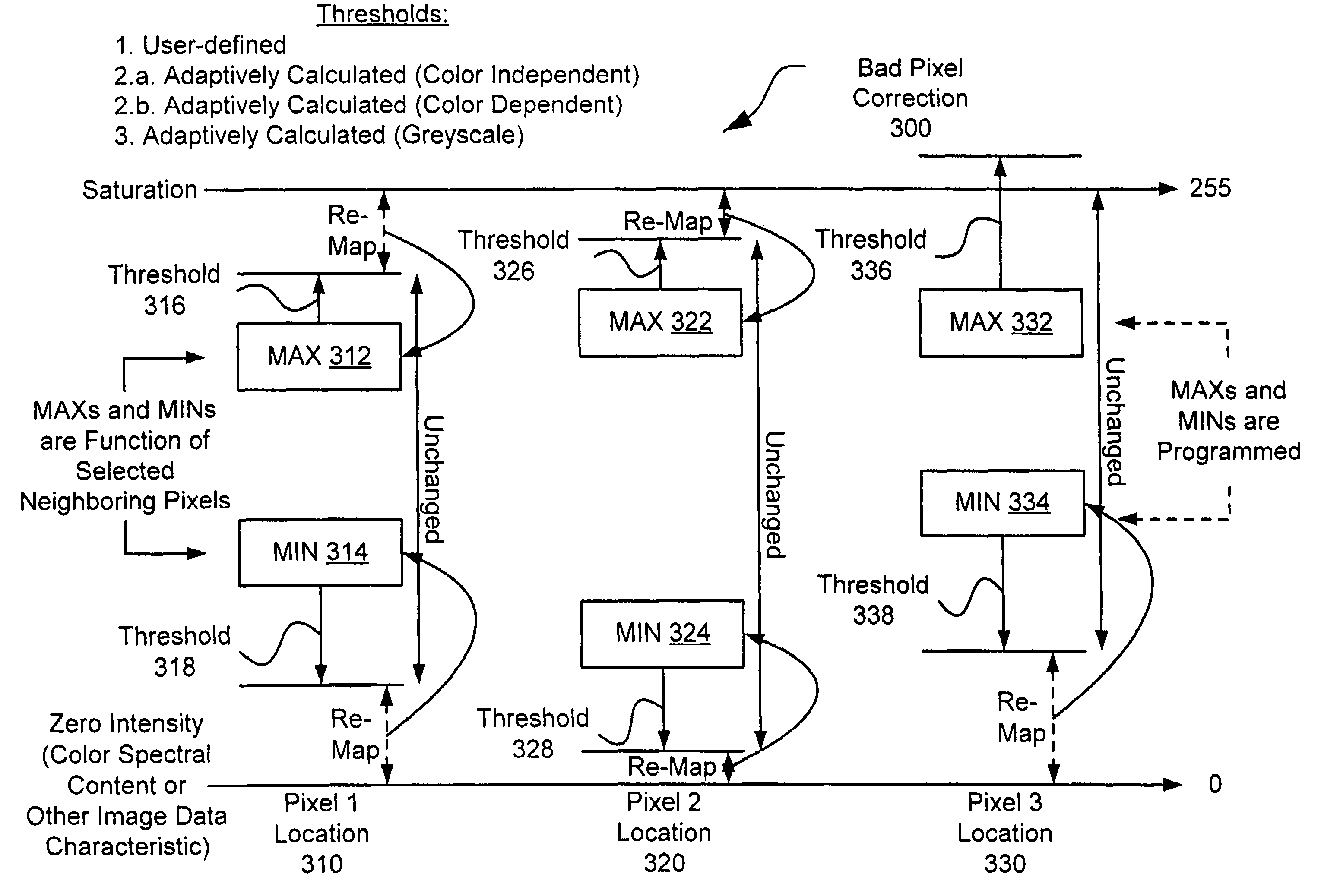
[0019]The present invention provides many important technical advantages. One important technical advantage of the present invention is a system and method for bad pixel detection and correction that use dynamic range thresholds to determine whether a pixel is bad. If the pixel is bad, then the pixel characteristic data is replaced with characteristic data for one of the adjacent pixels. The thresholds for the present invention can be adjusted to accommodate detail levels so as to provide bad pixel detection and correction that does not impair detail resolution.
[0020]Other systems, methods, features and advantages of the invention will be apparent to one with skill in the art upon examination of the following figures and detailed description. It is intended that all such additional systems, methods, features and advantages be included within this description, be within the scope of the invention, and be protected by the accompanying claims.

Problems solved by technology

One of the deficiencies of this conventional method of bad pixel correction is that three operations are needed to determine each median, and a total of twenty-one operations are performed for each pixel.
Another conventional method for correcting bad pixels is normal median filtering, but this method must also be performed on every pixel, and can undesirably smooth detail features on the image.

Method used


Image

  • Bad pixel correction while preserving features
  • Bad pixel correction while preserving features
  • Bad pixel correction while preserving features

Examples


Embodiment Construction

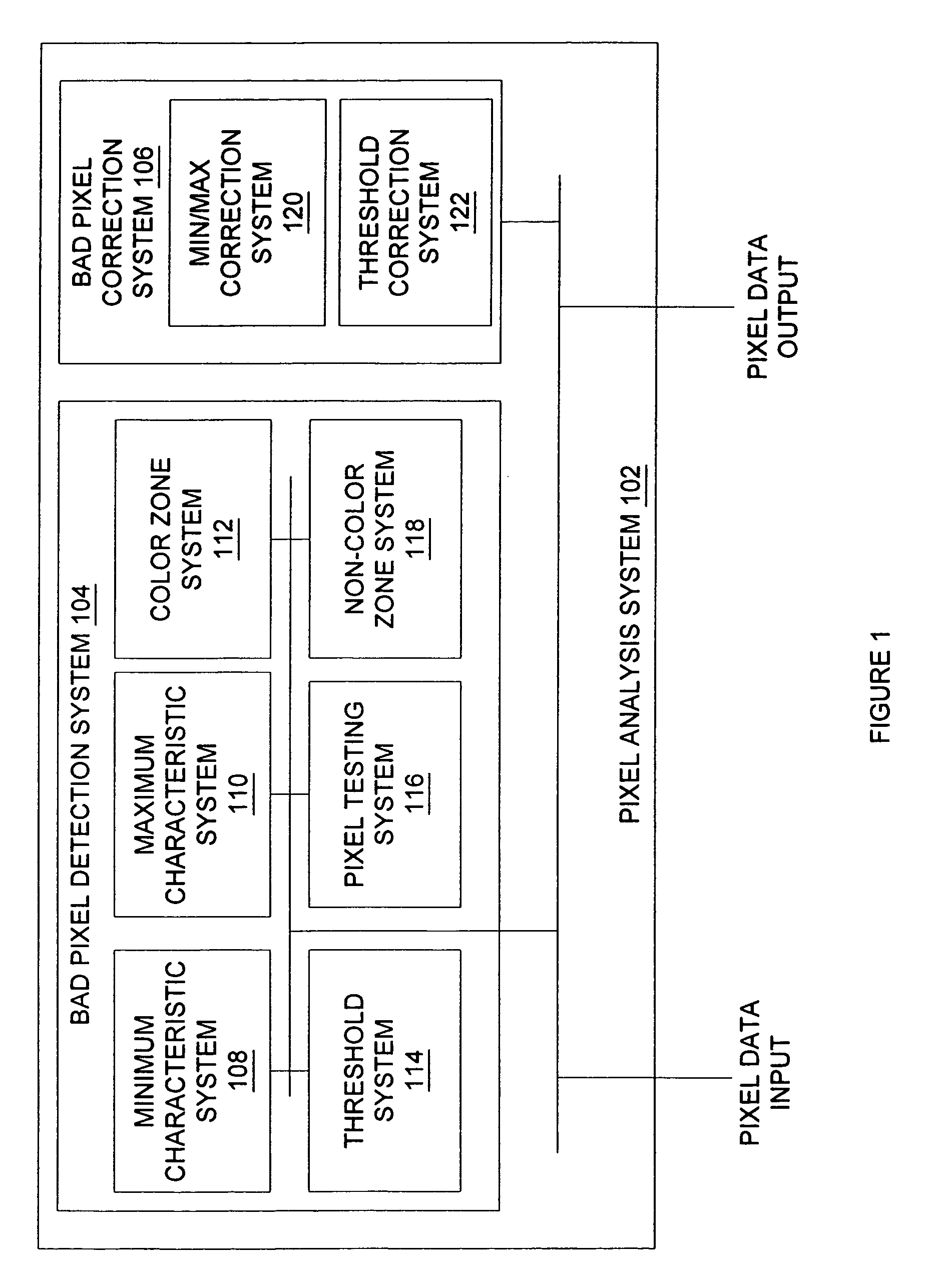
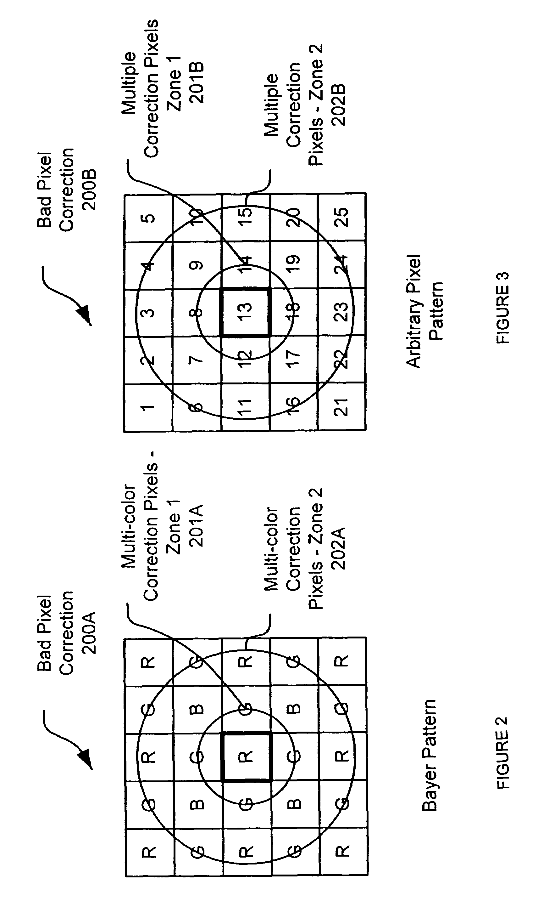
[0034]FIG. 1 is diagram of a system 100 for detecting and correcting bad pixels in accordance with an exemplary embodiment of the present invention. System 100 can use the characteristic data, such as intensity or brightness, for as few as two pixels adjacent to a test pixel to determine whether the test pixel is a bad pixel, and can also use the characteristic data for one of those adjacent pixels to determine the correction data for the pixel.

[0035]System 100 includes pixel analysis system 102, which can be implemented in hardware, software, or a suitable combination of hardware and software, and which can be one or more hardware systems, or one or more software systems operating on a suitable processing platform. As used herein, a hardware system can be one or more semiconductor devices, an application specific integrated circuit, a field programmable gate array, or other suitable systems or components. A software system can include one or more objects, agents, lines of code, thr...


PUM


Abstract

A pixel correction system is provided. The pixel correction system includes a dynamic range detection system that receives test pixel data and adjacent pixel data and determines whether the test pixel data is within minimum pixel characteristic data and maximum pixel characteristic data of the adjacent pixel data. For example, if the pixel characteristic data is intensity, the dynamic range detection system detects bad pixels by identifying those pixels having an intensity value that is greater than the maximum intensity value of an adjacent pixel, or less than the minimum intensity value of an adjacent pixel. A dynamic range correction system coupled to the dynamic range detection system adjusts the test pixel data if the test pixel data is not within the maximum pixel characteristic data and the minimum pixel characteristic data, such as by setting the test pixel data equal to the maximum pixel characteristic data if the test pixel data is greater than the maximum pixel characteristic data, and by setting the test pixel data equal to the minimum pixel characteristic data if the test pixel data is less than the minimum pixel characteristic data.

Description

BACKGROUND OF THE INVENTION[0001]1. Field of the Invention[0002]The invention relates to image processing and, more particularly, to bad pixel detection and correction within digital image processing that preserves features within the image.[0003]2. Related Art[0004]Conventional bad pixel detection and correction systems often employ multi-stage median filtering. The multi-stage median filtering is performed as shown below. For the 3×3 pixel array:[0005]a0, a1, a2[0006]a3, A, a4[0007]a5, a6, a7where a0, a1, a2, a3, a4, a5, a6, and a7 are the neighboring pixels, the multi-stage median filtering process is performed as follows:[0008]H=median (a3, A, a4)[0009]V=median (a1, A, a6)[0010]O=median (H, A, V)[0011]SE=median (a0, A, a7)[0012]NE=median (a5, A, a2)[0013]D=median (SE, A, NE)[0014]A′=median (O, A, D)[0015]One of the deficiencies of this conventional method of bad pixel correction is that three operations are needed to determine each median, and a total of twenty-one operations ar...

Claims


Application Information

Patent Timeline
Patent Type & Authority Patents(United States)
IPC IPC(8): G09G5/02G06K9/00H04N9/64G06K9/42G09G5/00H04N9/00
CPCG09G3/006G06T5/005G06T5/20H04N9/646G09G2330/10G06T2207/10024G06T5/77
Inventor BAO, YILIANG
Owner RE SECURED NETWORKS LLC
Learn More