Liquid crystal device, method for driving the same, and electronic apparatus

a liquid crystal device and driving method technology, applied in lighting and heating apparatus, instruments, heating types, etc., can solve the problems of reducing the brightness of the display, reducing the amount of light passing through the polarizer, and reducing the manufacturing cost and labor intensity. , to achieve the effect of efficient suppression of disclination in dot areas, low voltage and bright display

Active Publication Date: 2006-06-20
BOE TECH GRP CO LTD
View PDF22 Cites 23 Cited by
  • Summary
  • Abstract
  • Description
  • Claims
  • Application Information

AI Technical Summary

Benefits of technology

[0009]Accordingly, the present invention provides a liquid crystal device in which the disclination is efficiently suppressed in dot areas so as to obtain a bright display and in which alignment control of the liquid crystal molecules can be at a low voltage, and preferably a liquid crystal device having ease of fabrication.

Problems solved by technology

Unfortunately, in the homeotropic alignment mode, the tilt direction of the liquid crystal must be appropriately controlled.
Otherwise, disclination, which is a region where the liquid crystal molecules do not fall, occurs in the center of the dot area, thus disadvantageously decreasing brightness of the display.
Additionally, the liquid crystal molecules fallen radially about the disclination change the angle of the director of the liquid crystal molecules with respect to the polarizer in the dot areas, so that the amount of light passing through the polarizer is disadvantageously decreased.
Consequently, the complicated structure and the required high quality of the circuit disadvantageously make the fabrication difficult and costly.

Method used


Image

  • Liquid crystal device, method for driving the same, and electronic apparatus
  • Liquid crystal device, method for driving the same, and electronic apparatus
  • Liquid crystal device, method for driving the same, and electronic apparatus

Examples


first exemplary embodiment

[0040

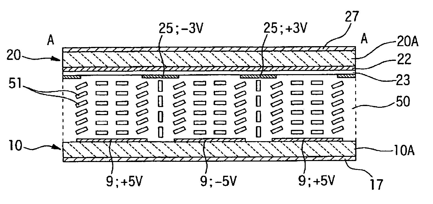
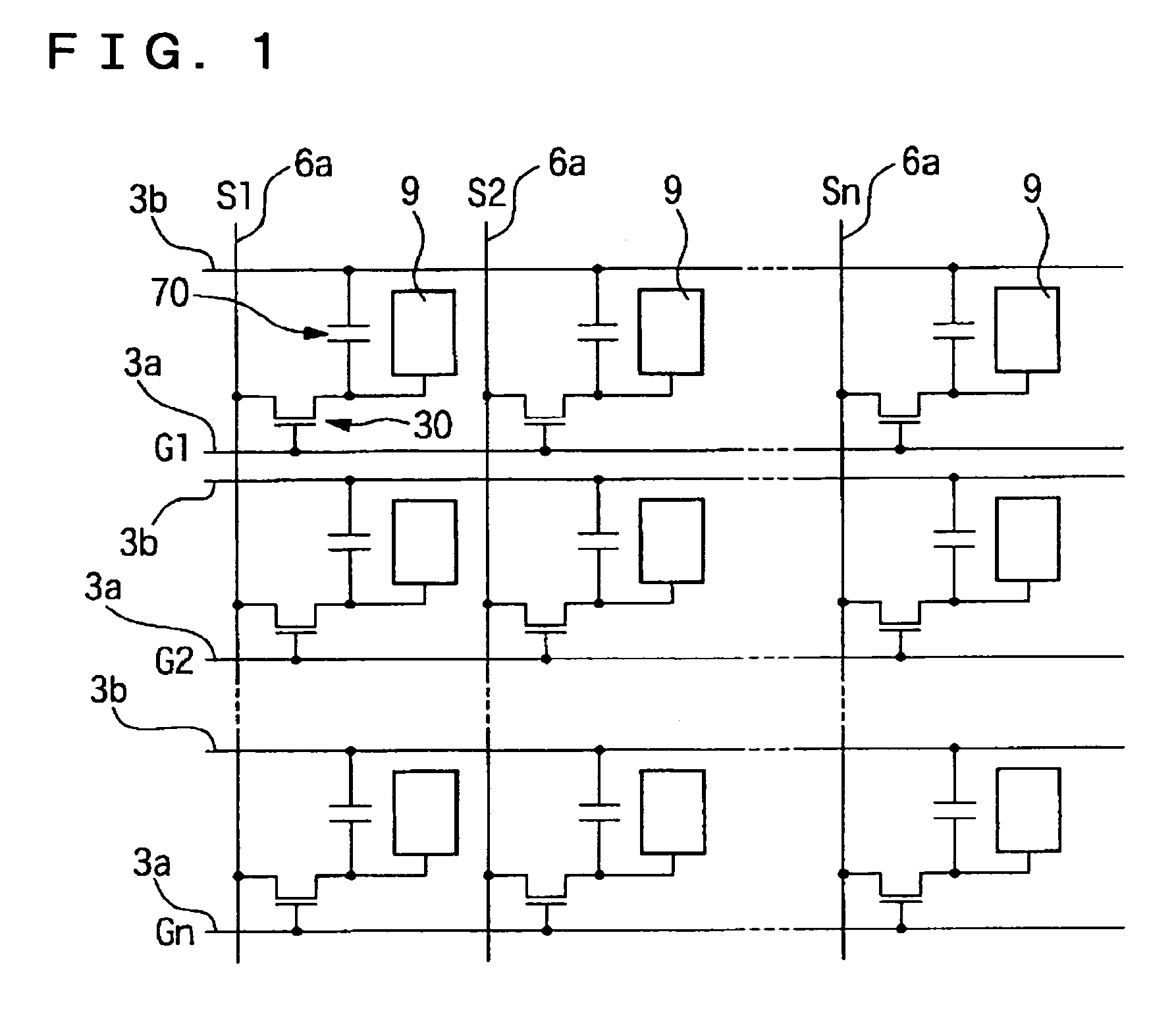
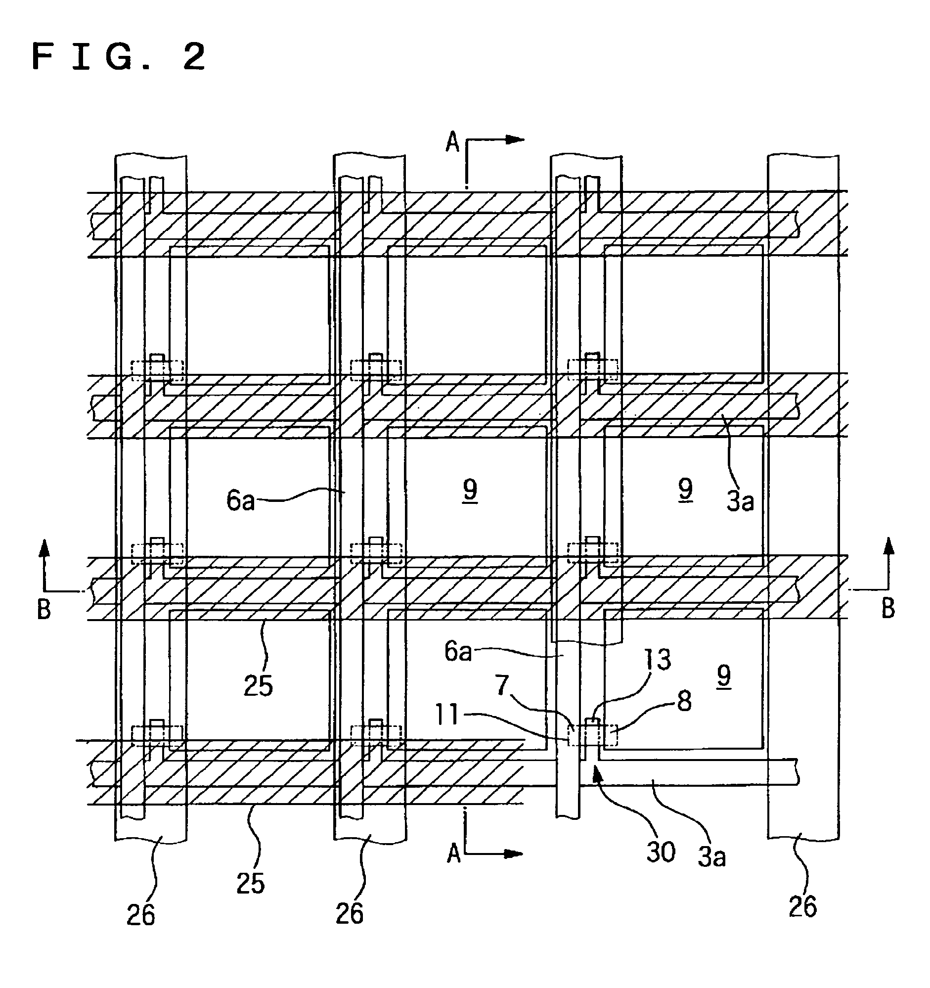
[0041]FIG. 1 is a schematic of an equivalent circuit of a plurality of dots arranged in a matrix, which constitute an image display area of a liquid crystal device according to an exemplary embodiment of the present invention. FIG. 2 is a plan view showing the structure of one dot on a TFT array substrate. FIGS. 3(A) and 3(B) are cross-sectional views showing the structure of the liquid crystal display device according to an exemplary embodiment of the present invention. FIG. 3(A) is a partial cross-sectional view along plane A—A in FIG. 2. FIG. 3(B) is a partial cross-sectional view of a counter substrate along plane B—B in FIG. 2. In the figures, the scales of the layers and the other elements are appropriately altered from the actual ones for enabling them to be easily viewed.

[0042]Referring to FIG. 1, in a liquid crystal device according to an exemplary embodiment of the present invention, pixel electrodes 9 and TFTs 30, which are switching elements controlling the correspo...

second exemplary embodiment

[0067

[0068]A second exemplary embodiment of the present invention will now be described with reference to FIG. 7. FIG. 7(A) is a partial plan view showing a structure of a liquid crystal device according to the embodiment of the present invention. FIG. 7(B) is a cross-sectional view of the structure along plane C—C in FIG. 7(A).

[0069]In the liquid crystal device according to the exemplary embodiment, except for the structure of the counter substrate, the basic structure is the same as that in the liquid crystal device according to the first exemplary embodiment. Accordingly, the same reference numerals are used in FIG. 7 and FIGS. 1 to 3 to identify the same elements and their detailed descriptions are omitted.

[0070]With reference to FIGS. 7(A) and 7(B), in the liquid crystal device according to the exemplary embodiment, stripe alignment control electrodes 25 are formed on the inner surface of counter substrate 20. An insulating film 23 covers the inner surface of the counter substr...


PUM

PropertyMeasurementUnit
voltagesaaaaaaaaaa
voltagesaaaaaaaaaa
voltagesaaaaaaaaaa

Abstract

To provide a liquid crystal device in which the occurrence of disclination is efficiently suppressed in a dot area, thereby allowing a bright display and the alignment control of the liquid crystal molecules can be carried out by applying low voltage, a liquid crystal device includes: an array substrate having pixel electrodes arranged in a matrix and switching elements corresponding to the respective pixel electrodes formed on a surfaces of the array substrate, a counter substrate opposing the array substrate, a liquid crystal layer including negative dielectric anisotropy liquid crystal disposed between the array substrate and the counter substrate, and stripe alignment control electrodes disposed on the liquid crystal layer facing surface of the counter substrate, each alignment control electrode extending along the boundaries of the pixel electrodes in plan view.

Description

BACKGROUND OF THE INVENTION[0001]1. Field of Invention[0002]The present invention relates to a liquid crystal device, a driving method of the liquid crystal device, and an electronic apparatus.[0003]2. Description of Related Art[0004]There are two types of liquid crystal alignment modes: a twisted nematic (hereinafter referred to as TN) mode, in which the liquid crystal molecules are, in the voltage OFF state, aligned substantially parallel to a substrate and twisted towards a direction perpendicular to the substrate, and a vertical, or homeotropic alignment mode, in which the liquid crystal molecules are vertically aligned. The TN mode has been used in the related art because of high reliability; however, much attention has been recently focused on liquid crystal devices using the homeotropic alignment mode due to several excellent characteristics.[0005]For example, in the homeotropic alignment mode, the state where the liquid crystal molecules are perpendicularly aligned relative ...

Claims


Application Information

Patent Timeline
Patent Type & Authority Patents(United States)
IPC IPC(8): G02F1/1337G02F1/13G02F1/1343G02F1/1335G02F1/133G02F1/1333G02F1/1368
CPCG02F1/1337G02F1/133707G02F2001/133742G02F1/133742B66B11/02F24F13/078
Inventor OKAZAKI, TSUYOSHIMAEDA, TSUYOSHIOZAWA, KINYA
Owner BOE TECH GRP CO LTD
Why Eureka
Try Eureka