Precision jitter-free frequency synthesis

a frequency synthesis and precision technology, applied in the field of integrated circuits, can solve the problems of not all possible phase shifts for all clock edges, digitally generated clock signals cannot be adjusted to a discrete accuracy, and certain limitations in these circuits

Inactive Publication Date: 2006-06-20
TEXAS INSTR INC
View PDF4 Cites 36 Cited by
  • Summary
  • Abstract
  • Description
  • Claims
  • Application Information

AI Technical Summary

Benefits of technology

[0016]It is therefore an object of this invention to provide a clock synthesis circuit and method of synthesizing a clock signal that provides a selectable clock frequency with no jitter.
[0017]It is a further object of this invention to provide such a circuit and method in which many different frequencies can be readily selected.
[0023]The present invention may be implemented in a clock synthesis circuit in which one or more frequency synthesis circuits utilize a “flying-adder” architecture, in which multiple available phases from a phase-locked loop are selectable according to a digital frequency select signal. According to this invention, a feedback frequency divide value within the phase-locked loop and a digital frequency select signal are selected in a manner that minimizes the frequency error between the generated clock signal and its desired frequency. The actual output frequency is thus determined from the combination of these values that directly generates, or most closely approximates, the desired frequency.

Problems solved by technology

However, these digitally-generated clock signals can only be adjusted to a discrete accuracy that corresponds to the minimum step size of the digital clock generation circuitry.
The resulting “phase jitter” is now a commonly specified parameter for digital clock circuitry, as this effect is often a limiting factor in the accuracy and performance of the circuit.
However, certain limitations are present in these circuits.
For example, not all possible phase shifts are available for all clock edges, because of the propagation delay through the selection circuitry.
Furthermore, these circuits must operate according to various timing constraints.
In this way, the number of synthesis paths can be increased arbitrarily, with the scaling limited by the performance of control circuits for the output multiplexer.
Each of these conventional circuits are vulnerable to jitter, however.

Method used


Image

  • Precision jitter-free frequency synthesis
  • Precision jitter-free frequency synthesis
  • Precision jitter-free frequency synthesis

Examples


Embodiment Construction

[0031]An exemplary implementation of the present invention in a generalized system environment will now be described. Those skilled in the art having reference to this specification will understand that this invention may be used in connection with a wide variety of applications. Examples of these systems include broadband or spread-spectrum transceivers, computer systems, video decoding and display systems, communications devices such as wireless telephone handsets, modems, and switching systems, and many others. These exemplary applications are noted because of their need for selectable frequency operation, particularly in the transmission and receipt of signals at multiple frequencies. The enumeration of these systems is presented by way of example only, and is not intended to limit the true scope of this invention as claimed.

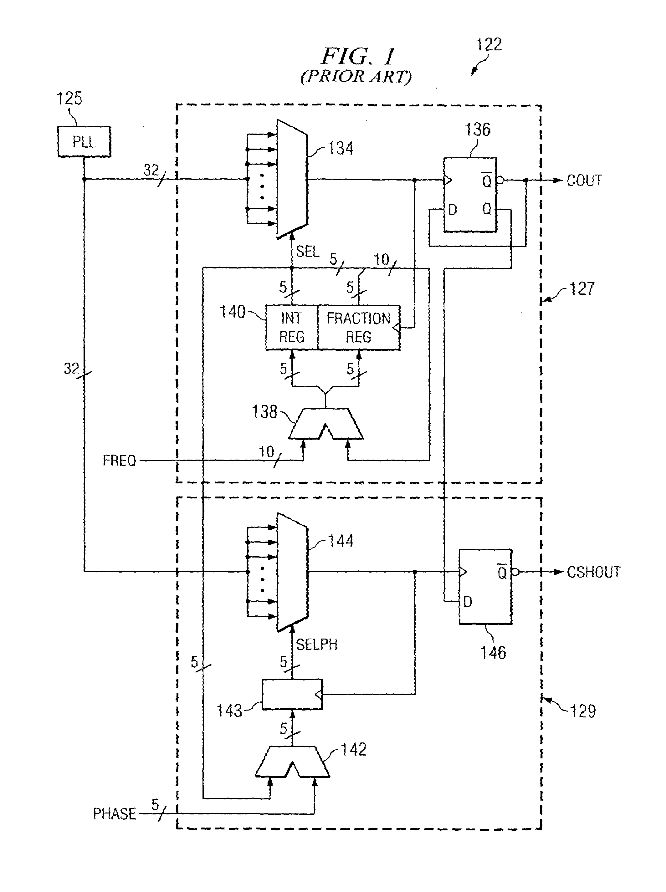
[0032]Prior to the detailed description of the clock generation circuit according to the preferred embodiment of the invention, however, it is useful to com...


PUM


Abstract

An electronic system (10) includes a phase-locked loop (30) and a frequency synthesis circuit (20), for generating a jitter-free output clock (CLK1, CLK2) at a desired frequency. The phase-locked loop (30) includes a voltage-controlled oscillator (37) that produces a number (N) of equally spaced clock phases at a frequency (fVCO) that depends also upon a programmable feedback frequency divider (38) and a prescale divider (32). The frequency synthesis circuit (20) generates the output clock (CLK1, CLK2) at a frequency under the control of a frequency select word (FREQ) that indicates the number of clock phases between successive clock edges. A central processing unit (12), either itself or from a look-up table (13), generates a feedback divide integer (M) and the frequency select word (FREQ) according to a desired frequency (f), by way of a minimization of the frequency error. The frequency of the output clock (CLK1, CLK2) can be generated in a jitter-free manner, since only integer values are used in the frequency synthesis circuit (20), at relatively low frequency error.

Description

CROSS-REFERENCE TO RELATED APPLICATIONS[0001]This application claims priority, under 35 U.S.C. §119(e), of Provisional Application No. 60 / 395,882, filed Jul. 15, 2002.STATEMENT REGARDING FEDERALLY SPONSORED RESEARCH OR DEVELOPMENT[0002]Not applicable.BACKGROUND OF THE INVENTION[0003]This invention is in the field of integrated circuits, and is more specifically directed to clock synthesis circuits for generating periodic signals at selected frequencies for use in integrated circuits.[0004]As is fundamental in the art, many modem electronic systems now include numerous integrated circuits that operate in conjunction with one another. In complex high performance systems such as modern personal computers and workstations, these integrated circuits are synchronized with a system clock. In consumer-oriented systems such as televisions and home theaters, for example, system operation is synchronized with respect to a synchronization pulse that is included within the display signal itself....

Claims


Application Information

Patent Timeline
Patent Type & Authority Patents(United States)
IPC IPC(8): H03D3/24H03L7/099H03L7/183
CPCH03L7/183H03L7/0996
Inventor XIU, LIMINGYOU, ZHIHONG
Owner TEXAS INSTR INC
Why Eureka
Try Eureka